
Modbus Simulation – Essential Skills for Beginners
In the field of industrial automation, we often encounter various communication protocols, such as Profibus, ControlNet, Ethernet, Canopen, and Modbus. Among these, the Modbus protocol is the most widely used, free, and open-source, and is supported by almost all manufacturers’ industrial equipment.
When working on engineering projects, we may need to conduct communication tests, but we may not have the corresponding communication devices available for testing. Therefore, we require some simulation testing software. The software we use most frequently is ModScan, which can be used for Modbus TCP communication, Modbus RTU communication, and Modbus ASCII communication, acting as a master to collect data from slave devices. It can send commands to slave devices (which must be intelligent devices using the Modbus protocol), and after the slave responds, the corresponding register data can be returned on the monitoring interface.
So how do we conduct the tests?
First, establish the hardware connection. Install the ModScan software on the PC, which serves as the master to collect data. You will also need an intelligent device that supports the Modbus protocol as the slave. Generally, a PC only has USB ports, so a USB to serial to RS485 converter is required to connect to the intelligent slave device. This scenario is for devices that support the Modbus-RTU protocol with an RS485 interface; if the intelligent slave supports the Modbus TCP/IP protocol, you only need to connect the PC and the slave device with an Ethernet cable.
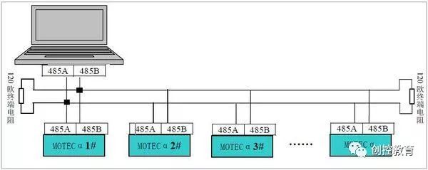
RS485 Connection
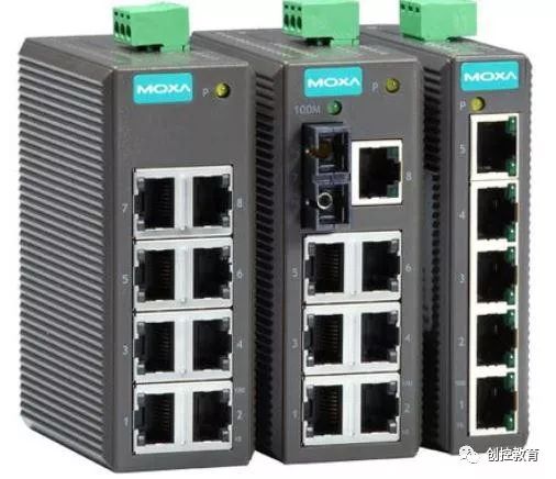
If it is a TCP connection, only one device can be directly connected with an Ethernet cable. If there are multiple devices, an industrial Ethernet switch is needed to connect all devices to the switch, allowing access to different devices through different IP addresses.
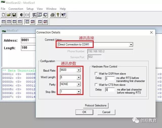
Second, open the ModScan software to set the communication parameters. If it is RS485 communication, select the serial port and configure the baud rate (typically defaulting to 9600), data length (8 bits), parity bit (no parity), and stop bit (1 bit), as shown in the figure:
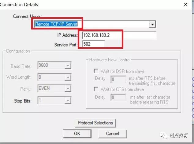
If it is Modbus TCP communication, set the communication connection as shown in the figure, select TCP/IP, and enter the slave device’s IP address and port number (default is 502).
Third, set the communication registers. Fill in the starting address for the register in Address, Length for the length, 03:HOLDING REGISTER for the register type, indicating a holding register, and Device ID for the slave’s station number. If it is Modbus RTU, you need to enter the slave address here; if it is Modbus TCP communication, you do not need to enter it. If a serial server is used, you need to enter the slave address as well. The Number of Polls / Valid Slave Responses indicates the number of data transmission and reception, allowing you to see if there are any packet losses. The middle area displays detected data from the slave, and if there is an alarm, it indicates a communication failure.
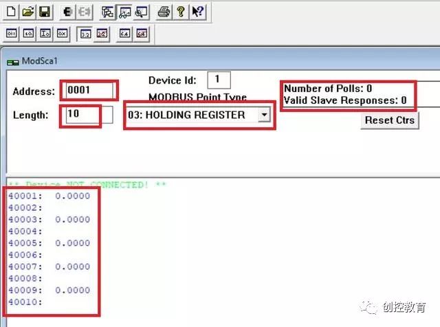
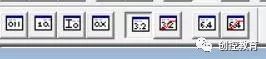
Select the data type as shown in the figure. Currently, we are using 32-bit floating point type, as well as bit type, integer, double-precision floating point type, etc. For floating point types, high-low byte swapping can also be set.
Fourth, we conduct communication tests using Modbus TCP, setting the IP communication address to: 192.168.1.10, with the port number: 502. Ensure that the PC’s IP address and the slave’s IP address (192.168.1.10) are on the same subnet, for example: 192.168.1.20.
We want to read the slave register as follows: holding register, so select function code: 03, starting register address: 1, data type: 32-bit floating point type, and set the number of registers to read: 10, then click connect, as shown in the figure:
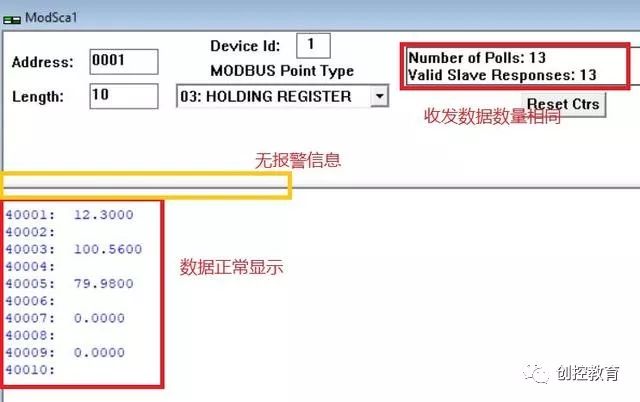
From the figure, we can see that there are no alarm messages on the main interface, and the data transmission and reception counts are the same, indicating no data loss. The corresponding register shows data, confirming that the communication was successful. Mission accomplished!!!
(Content sourced from the internet, copyright belongs to the original author)
Disclaimer: If there are copyright issues, please contact for removal!No individual or organization bears any legal responsibility.