The Most Comprehensive Free Industrial Control Software!
(Click the red text above to get free materials)
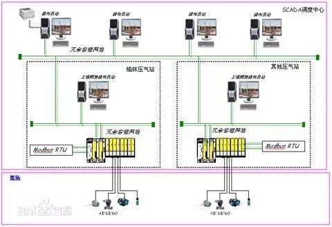
Introduction:The ModBus network is an industrial communication system formed by connecting programmable controllers with intelligent terminals and computers through common lines or local private lines. Its system structure includes both hardware and software. It can be used for various data collection and process monitoring.
The ModBus network has only one host, and all communications are initiated by it. The network can support as many as 247 remote slave controllers, but the actual number of slaves supported depends on the communication devices used. By using this system, each PC can exchange information with the central host without affecting its own control tasks.
Understanding the Modbus communication protocol allows you to perform communication tests on-site using various third-party software.
The Modbus protocol includes ASCII, RTU, TCP, etc., and does not specify the physical layer. This protocol defines the message structure that controllers can recognize and use, regardless of the network used for communication. Standard Modicon controllers use RS232C to implement serial Modbus. Modbus’s ASCII and RTU protocols specify the message, data structure, commands, and response methods. Data communication uses the Master/Slave method, where the Master sends a data request message, and the Slave sends data back to the Master in response to the correct message received; the Master can also directly send messages to modify the Slave’s data, achieving bidirectional read and write.
The Modbus protocol requires data verification; in serial protocols, in addition to parity checking, the ASCII mode uses LRC verification, while the RTU mode uses 16-bit CRC verification. However, the TCP mode does not specify additional verification because the TCP protocol is a reliable connection-oriented protocol. Additionally, Modbus uses a master-slave method for timed data transmission. In practical use, if a slave site disconnects (e.g., due to a fault or shutdown), the Master can diagnose it, and when the fault is repaired, the network can automatically reconnect. Therefore, the reliability of the Modbus protocol is relatively good.
For the Modbus ASCII, RTU, and TCP protocols, TCP and RTU protocols are very similar; we simply need to remove the two-byte checksum from the RTU protocol, then add five 0s and a 6 at the beginning of the RTU protocol and send it out via TCP/IP network protocol.
Communication transmission is divided into an independent information header and the encoded data sent. The following communication transmission method definitions are compatible with the ModBus RTU communication protocol:
Initial Structure = ≥4 bytes of time
Address Code = 1 byte
Function Code = 1 byte
Data Area = N bytes
Error Check = 16-bit CRC code
End Structure = ≥4 bytes of time
Address Code:The address code is the first byte of the communication transmission. This byte indicates which slave, set by the user, will receive the information sent by the host. Each slave has a unique address code, and the response will begin with its respective address code. The address code sent by the host indicates the address of the slave to which it will send, while the address code sent by the slave indicates the address of the slave that is responding.
Function Code:The second byte of the communication transmission. The ModBus communication protocol defines function numbers from 1 to 127. This instrument only utilizes a portion of the function codes. As a request from the master, it tells the slave what action to perform through the function code. As a response from the slave, the function code sent by the slave is the same as the one sent by the master, indicating that the slave has responded to the master’s operation. If the highest bit of the function code sent by the slave is 1 (for example, if the function code is greater than 127), it indicates that the slave did not respond to the operation or an error occurred.
Data Area:The data area varies according to different function codes. The data area can be actual values, set points, or addresses sent by the master to the slave or from the slave to the master.
CRC Code:A two-byte error detection code.
When a communication command is sent to the instrument, the device with the corresponding address code receives the communication command, removes the address code, reads the information, and if there are no errors, executes the corresponding task; then sends the execution result back to the sender. The returned information includes the address code, the function code of the executed action, the result data after the action, and the error check code. If there is an error, no information is sent.
1. Information Frame Structure
Address Code Function Code Data Area Error Check Code
8 bits 8 bits N × 8 bits 16 bits
Address Code:The address code is the first byte (8 bits) of the information frame, ranging from 0 to 255. This byte indicates which slave, set by the user, will receive information sent by the host. Each slave must have a unique address code, and only slaves that match the address code can respond. When a slave returns information, the corresponding address code indicates where the information comes from.
Function Code:The function code sent by the master tells the slave what task to perform. The function codes listed in Table 1-1 have specific meanings and operations.
Data Area:The data area contains what actions the slave needs to perform or the information returned from the slave. This information can be values, reference addresses, etc. For example, if the function code tells the slave to read the value of a register, the data area must include the starting address of the register to be read and the length of the read. The addresses and data information vary for different slaves.
Error Check Code:The master or slave can use the check code to determine whether the received information has an error. Sometimes, due to electronic noise or other interferences, information may undergo slight changes during transmission, and the error check code ensures that the master or slave does not act on erroneous information during transmission. This increases the system’s safety and efficiency. The error check uses the CRC-16 verification method.
Note: The format of the information frame is generally the same: address code, function code, data area, and error check code.
2. Error Check
The Redundant Cyclic Code (CRC) consists of 2 bytes, that is, 16 bits in binary. The CRC code is calculated by the sending device and placed at the end of the sent information. The receiving device recalculates the CRC code of the received information and compares it with the received CRC code. If the two do not match, it indicates an error.
|
Function Code |
Name |
Function |
|
1 |
Read Coil Status |
Obtain the current status of a group of logical coils (ON/OFF) |
|
2 |
Read Input Status |
Obtain the current status of a group of switch inputs (ON/OFF) |
|
3 |
Read Holding Registers |
Obtain the current binary values in one or more holding registers |
|
4 |
Read Input Registers |
Obtain the current binary values in one or more input registers |
|
5 |
Force Single Coil |
Force the ON/OFF state of a logical coil |
|
6 |
Preset Single Register |
Load a specific binary value into a holding register |
|
7 |
Read Exception Status |
Obtain the ON/OFF status of 8 internal coils, whose addresses are determined by the controller |
|
8 |
Return Diagnostic Check |
Send a diagnostic check message to the slave for communication processing evaluation |
|
9 |
Programming (only for 484) |
Allows the master to simulate the programmer’s role and modify the logic of the PC slave |
|
10 |
Inquiry (only for 484) |
Allows the master to communicate with a slave that is performing a long program task, inquiring whether the slave has completed its operation task; this function code can only be sent after sending a message with function code 9 |
|
11 |
Read Event Count |
Allows the master to send a single inquiry and immediately determine whether the operation was successful, especially if a communication error occurs with this command or other responses |
|
12 |
Read Communication Event Log |
Allows the master to retrieve the ModBus transaction processing communication event log from each slave. If a transaction is completed, the log will provide information about errors |
|
13 |
Programming (184/384 484 584) |
Allows the master to simulate programming functions to modify the logic of the PC slave |
|
14 |
Inquiry (184/384 484 584) |
Allows the master to communicate with a slave performing a task, periodically inquiring whether the slave has completed its program operation; this function code can only be sent after sending a message containing function code 13 |
|
15 |
Force Multiple Coils |
Force the ON/OFF state of a series of continuous logical coils |
|
16 |
Preset Multiple Registers |
Load specific binary values into a series of continuous holding registers |
|
17 |
Report Slave Identification |
Allows the master to determine the type of addressed slave and the status of the slave’s running indicator |
|
18 |
(884 and MICRO 84) |
Allows the master to simulate programming functions to modify the logic of the PC status |
|
19 |
Reset Communication Link |
After a non-modifiable error occurs, the slave resets to a known state, allowing the sequence bytes to be reset |
|
20 |
Read General Parameters (584L) |
Display data information in the extended memory file |
|
21 |
Write General Parameters (584L) |
Write or modify general parameters into the extended storage file |
|
22~64 |
Reserved for extended functions |
|
|
65~72 |
Reserved for user functions |
Reserved for user function expansion coding |
|
73~119 |
Illegal Function |
|
|
120~127 |
Reserved |
Reserved for internal use |
|
128~255 |
Reserved |
Used for abnormal responses |
Among these function codes, the most commonly used are function codes 1, 2, 3, 4, 5, and 6, which can be used to perform read and write operations on digital and analog quantities of the lower machine.
1. Command 01, Read Readable and Writable Digital Registers (Coil Status):
The computer sends the command: [Device Address] [Command Number 01] [Starting Register Address High 8 Bits] [Low 8 Bits] [Number of Registers to Read High 8 Bits] [Low 8 Bits] [CRC Check Low 8 Bits] [CRC Check High 8 Bits]

Example: [11][01][00][13][00][25][CRC Low][CRC High]
Meaning as follows:
<1>Device Address: Multiple devices can be connected on a 485 bus, and the device address here indicates which device to communicate with. In the example, it is communicating with device number 17 (decimal 17 is hexadecimal 11).
<2>Command Number 01: The command number for reading digital quantities is fixed at 01.
<3>Starting Address High 8 Bits, Low 8 Bits: Indicates the starting address of the switch quantity to be read (starting address is 0). For example, in the example, the starting address is 19.
<4>Register Count High 8 Bits, Low 8 Bits: Indicates how many switch quantities to read starting from the starting address. In the example, it is 37 switch quantities.
<5>CRC Check: Check from the beginning to here.
Device Response: [Device Address] [Command Number 01] [Number of Returned Bytes] [Data1][Data2]…[DataN] [CRC Check High] [CRC Check Low]

Example: [11][01][05][CD][6B][B2][0E][1B] [CRC High] [CRC Low]
Meaning as follows:
<1>Device Address and Command Number are the same as above.
<2>Returned Byte Count: Indicates the number of data bytes, which is the value of n in Data1, Data2…n.
<3>Data1…n: Since each data is an 8-bit number, each data represents the value of 8 switch quantities, where each bit being 0 indicates the corresponding switch is off, and 1 indicates it is on. For example, in the example, it indicates that switch number 20 (index number 19) is on, switch number 21 is off, switch number 22 is on, switch number 23 is on, switch number 24 is off, switch number 25 is off, switch number 26 is on, switch number 27 is on… If the number of switch quantities queried is not a multiple of 8, then the high part of the last byte is meaningless and set to 0.
<4>CRC check as above.
2. Command 05, Write Digital Quantity (Coil Status):
The computer sends the command: [Device Address] [Command Number 05] [Register Address to be Set High 8 Bits] [Low 8 Bits] [Data to be Set High 8 Bits] [Low 8 Bits] [CRC Check Low 8 Bits] [CRC Check High 8 Bits]

Example: [11][05][00][AC][FF][00][CRC High][CRC Low]
Meaning as follows:
<1>Device Address is the same as above.
<2>Command Number: The command number for writing digital quantities is fixed at 05.
<3>Register Address to be Set High 8 Bits, Low 8 Bits: Indicates the address of the switch to be set.
<4>Data to be Set High 8 Bits, Low 8 Bits: Indicates the state of the switch to be set. In the example, it indicates closing the switch. Note that only [FF][00] indicates closing and [00][00] indicates opening; other values are illegal.
<5>Note that this command can only set the state of one switch at a time.
Device Response: If successful, the command sent by the computer is returned as is; otherwise, no response is given.
3. Command 03, Read Readable and Writable Analog Registers (Holding Registers):
The computer sends the command: [Device Address] [Command Number 03] [Starting Register Address High 8 Bits] [Low 8 Bits] [Number of Registers to Read High 8 Bits] [Low 8 Bits] [CRC Check High 8 Bits] [CRC Check Low 8 Bits]

Example: [11][03][00][6B][00][03] [CRC High][CRC Low]
Meaning as follows:
<1>Device Address is the same as above.
<2>Command Number: The command number for reading analog quantities is fixed at 03.
<3>Starting Address High 8 Bits, Low 8 Bits: Indicates the starting address of the analog quantity to be read (starting address is 0). For example, in the example, the starting address is 107.
<4>Register Count High 8 Bits, Low 8 Bits: Indicates how many analog quantities to read starting from the starting address. In the example, it is 3 analog quantities. Note that in the returned information, one analog quantity requires two bytes to return.
Device Response: [Device Address] [Command Number 03] [Number of Returned Bytes] [Data1][Data2]…[DataN] [CRC Check High] [CRC Check Low]

Example: [11][03][06][02][2B][00][00][00][64] [CRC High] [CRC Low]
Meaning as follows:
<1>Device Address and Command Number are the same as above.
<2>Returned Byte Count: Indicates the number of data bytes, which is the value of n in Data1, Data2…n. In the example, it returns the values of 3 analog quantities, as one analog quantity requires 2 bytes, so a total of 6 bytes.
<3>Data1…n: Where [Data1][Data2] are the high and low 8 bits of the first analog quantity, [Data3][Data4] are the high and low 8 bits of the second analog quantity, and so on. In the example, the returned values are 555, 0, 100.
<4>CRC check as above.
4. Command 06, Write Single Analog Quantity Register (Holding Register):
The computer sends the command: [Device Address] [Command Number 06] [Register Address to be Set High 8 Bits] [Low 8 Bits] [Data to be Set High 8 Bits] [Low 8 Bits] [CRC Check High 8 Bits] [CRC Check Low 8 Bits]

Example: [11][06][00][01][00][03] [CRC High] [CRC Low]
Meaning as follows:
<1>Device Address is the same as above.
<2>Command Number: The command number for writing analog quantities is fixed at 06.
<3>Register Address to be Set High 8 Bits, Low 8 Bits: Indicates the address of the analog quantity register to be set.
<4>Data to be Set High 8 Bits, Low 8 Bits: Indicates the analog quantity data to be set. For example, in the example, it sets the value of register 1 to 3.
<5>Note that this command can only set the state of one analog quantity at a time.
Device Response: If successful, the command sent by the computer is returned as is; otherwise, no response is given.
5. Command 16, Write Multiple Analog Quantity Registers (Holding Registers):
The computer sends the command: [Device Address] [Command Number 16] [Register Address to be Set High 8 Bits] [Low 8 Bits] [Data Count High 8 Bits] [Data Count Low 8 Bits] [Data to be Set High 8 Bits] [Low 8 Bits][……][……] [CRC Check High 8 Bits] [CRC Check Low 8 Bits]
Example: [11][16][00][01][00][01][00][05] [CRC High] [CRC Low]
Meaning as follows:
<1>Device Address is the same as above.
<2>Command Number: The command number for writing analog quantities is fixed at 16.
<3>Register Address to be Set High 8 Bits, Low 8 Bits: Indicates the address of the analog quantity register to be set.
<4>Data Count High 8 Bits, Low 8 Bits: Indicates the number of data to be set; here it is 1.
<5>Data to be Set High 8 Bits, Low 8 Bits: Indicates the analog quantity data to be set. For example, in the example, it sets the value of register 1 to 5.
Device Response: If successful, the command sent by the computer is returned as is; otherwise, no response is given.
Device Response: [Device Address] [Command Number 16] [Register Address to be Set High 8 Bits] [Low 8 Bits] [Data Count High 8 Bits] [Data Count Low 8 Bits] [CRC Check High] [CRC Check Low], as in the example returns:
[11][16][00][01][00][01] [CRC High] [CRC Low]
Recommended by the EditorHOT
 The Most Comprehensive Industrial Control Software Links Are Free!
 With these 6000 materials in hand, salaries can easily double!
 Japan’s Fully Automated Lunch Box Production Line, No One in the Entire Factory
 We Need More Technicians, Not PhDs!
 As an Industrial Control Professional, How to Make Yourself a Hot Talent?
 The Industrial Control Help Summer Teacher Training Camp Visits BYD Auto Factory
 End
End 
▣ Source:I Love Learning PLC
▣ Statement:This article’s materials are collected from the internet, edited and organized by Industrial Control Help. The videos, images, and text used in the article are copyrighted by the original authors. If there are any copyright issues, please contact 15388920506 (WeChat same number) promptly, and we will confirm the copyright and pay remuneration according to national regulations!
▣ Suggestion: There may be omissions or errors in the article. Please feel free to express your opinions in the comment area; what you know may be exactly what others want to understand! This way, we can help more people learn more! Thank you for your support!