Hello everyone, good evening!

Beginner’s Guide to TIA Portal: MODBUS-RTU Communication Configuration
Continuing from the previous article, we will explain how to use MODBUS communication commands.
MODBUS communication requires three commands:
① MB_COMM_LOAD command
② MB_MASTER command (Master command)
③ MB_SLAVE command (Slave command)
The communication commands are located in Communication – Communication Processor – MODBUS (Figure 1-1):
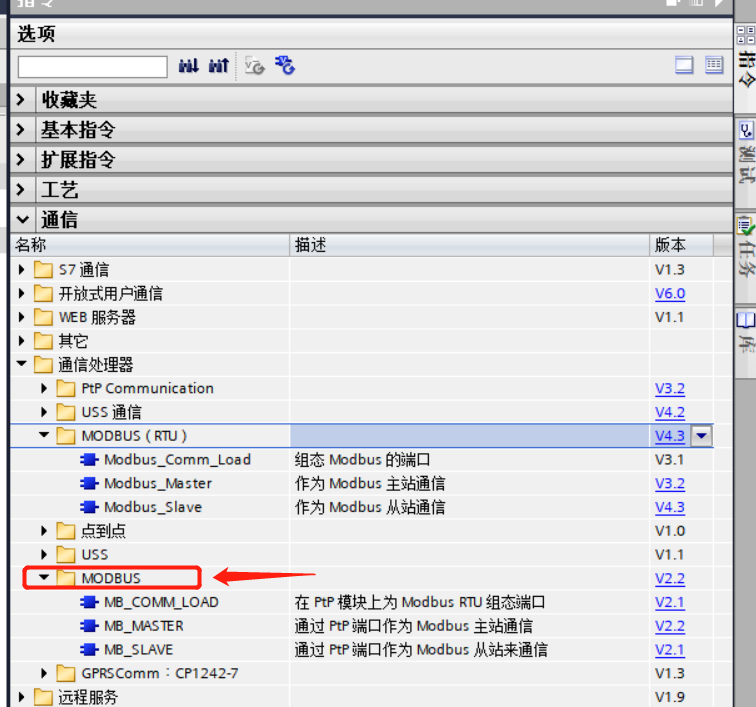 Figure 1-1
In the communication processor, there are MODBUS (RTU) and MODBUS;
They have certain differences:
First, let’s talk about MODBUS (RTU). In the command folder, there are three commands (Figure 1-1) that configure the MODBUS port for both MODBUS master communication and MODBUS slave communication.
When in use, it can only be applied to the serial modules of the PROFINET or profibus-dp on the et200mp or et200sp; it can be used when using MODBUS-RTU communication; you can also choose the firmware version 4.1 for the 1200 PLC and version 2.1 for the communication module CM1241, and you can also use the MODBUS (RTU) commands.
Similarly, the MODBUS command folder also contains three commands; the PLC extension’s CM1241 communication module or the communication signal board CB1241 will often use MODBUS commands when selecting commands.
Introducing the commands in the MODBUS folder:
The first: mb-load, this command is used to set the MODBUS communication port;
The second: master command, which is the command when the PLC acts as the MODBUS master;
The third: mb-slave command, which is used when the PLC acts as the MODBUS slave.
It can be seen that in the MODBUS commands, there are references to PTP modules or PTP ports, indicating that the communication uses the communication module extended on the PLC side.
We choose the S7-1200 PLC series 1215CDC/DC/DC PLC, version 4.2, using the communication module CM1241 (RS485) to implement communication functions, with commands from the MODBUS folder.
After completing hardware configuration, drag the commands into Main:
The first command is MB_COMM_LOAD, used for configuring the port.
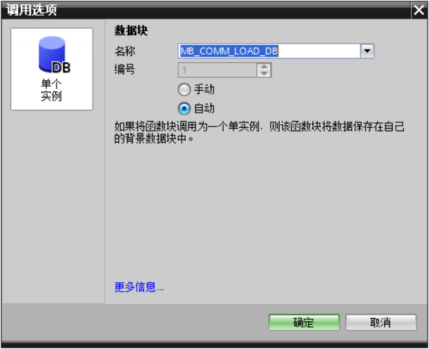 Figure 1-2
The name and number can be changed, but it is not recommended to modify the number;
Pin Introduction:
REQ: Executes the command on the rising edge;
Port: Indicates the hardware identifier of the module expansion (demonstrating how to add)
BAUD: Baud rate; this is selected based on the baud rate of both communication parties.
(Commonly used: 9600)
PARTY: Parity code (options are 0, 1, 2)
0: No check, 1: Odd check, 2: Even check.
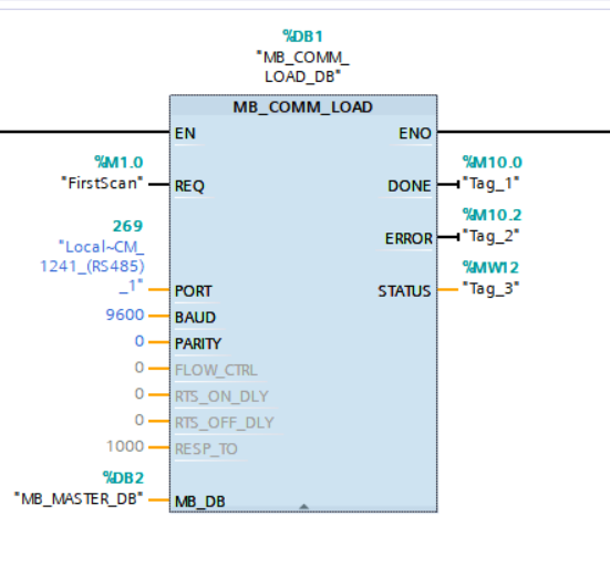 Figure 1-3
The four gray pins FLOW_CRTL, RST_ON_DLY, RST_OFF_DLY, RESP_TO are used for RS232 communication and are not used here.
MB_DB: Represents the DB block above the MB_MASTER or MB_SLAVE command; if your current PLC is a slave, then what you fill here is the DB block of the MB_SLAVE command;
Output Pins:
DONE, completion bit,
ERROR, fault status display bit,
STATUS, this is the status storage, storing error codes.
The MB_COMM_LOAD command only needs to be activated once per port during the execution of the program.
As shown above, you can use the first cycle function of the system memory bit, or create an organization block OB100 (Startup) and place the command inside OB100.
Today, this is the sharing of “Beginner’s Guide to TIA Portal 29 (MODBUS-RTU Communication Configuration)” by Xiaozhi. You can bookmark it for use. If you encounter problems or have misunderstandings, you can privately message or comment. If you like, please follow Xiaozhi, like, and share, thank you!
Next episode preview… (Video demonstration of MODBUS-RTU communication)