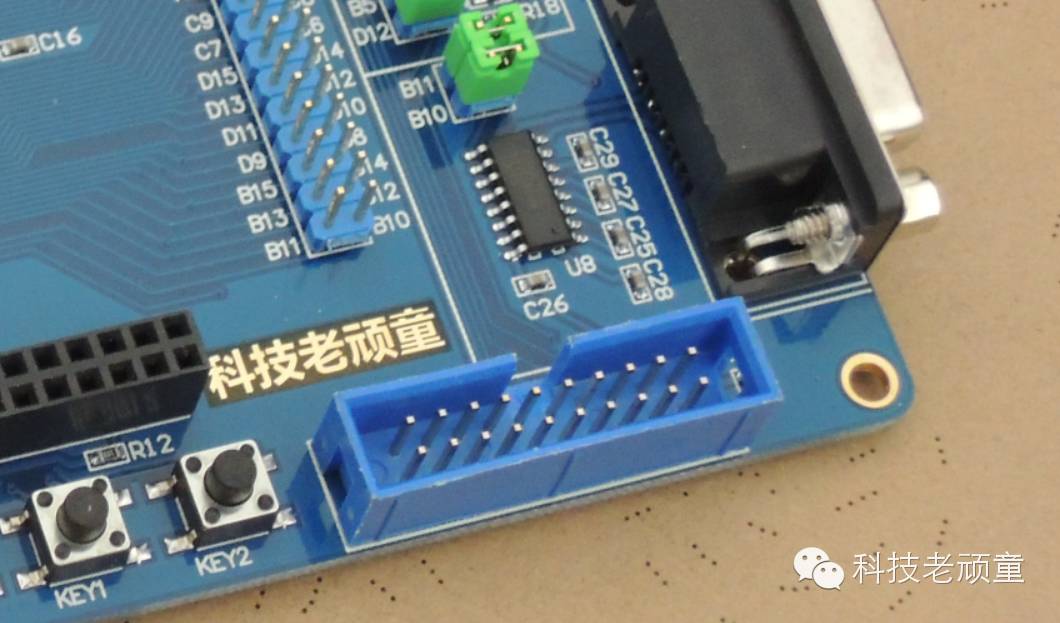
What is the JTAG Interface?
Visually, the JTAG interface is the blue 20-pin connector shown in the image above.
What is the Purpose of the JTAG Interface?
-
To download programs to the microcontroller.
-
To debug the microcontroller online, such as step debugging, power-off debugging, viewing register values, etc.
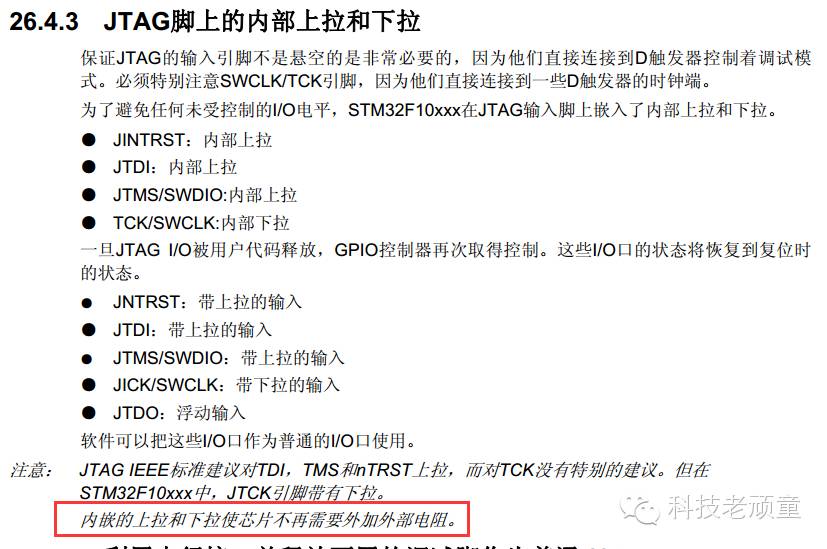
Does the JTAG interface for STM32 need external pull-up or pull-down resistors?
Answer: It can work with or without them. (There is no need to discuss which is correct)
Why can it work without them?
Practical evidence: It can function normally without them.
Theoretical basis: The STM32 reference manual explains this; please refer to the text circled in red in the image below:
JTAG Circuit Diagram:
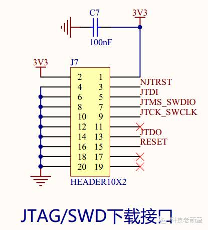
The JTAG interface is also the SWD interface; JTAG uses 6 pins, while SWD uses 2 pins. (This does not include the power supply pins.)
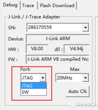
STM32 supports both JTAG and SWD modes, which can be switched in software as shown in the image below:
For electronics learning, please follow the WeChat public account: Tech Old Child.
Click the 【Read the Original】 button below to enter the most popular electronic engineer WeChat forum to share your insights!