Hardware Introduction
Currently, there are mainly two types of AMD-Xilinx FPGA-JTAG in China: one is the official development board:
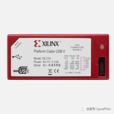
The second is the newly launched smart lynq (faster and more functional):
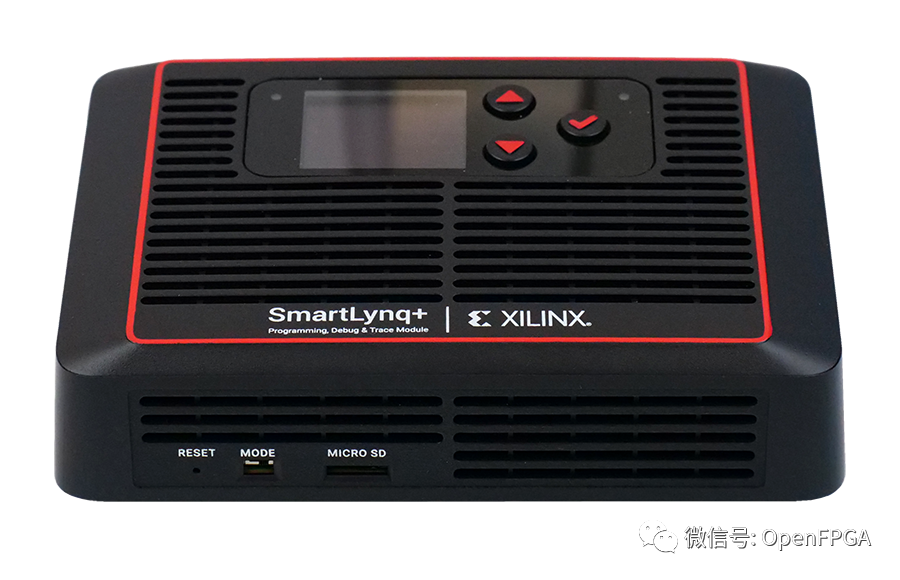
The price discourages a large number of people:

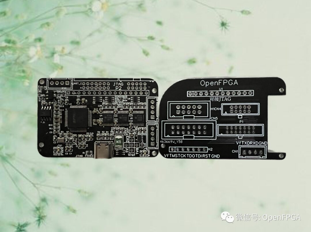
The second type is domestic, with various kinds that I won’t show images of. Domestic JTAG basically uses reverse-engineered Digilent onboard JTAG, implemented with FT232Hx or FT2232Hx series chips and reverse-engineered firmware. However, recently the prices of FT232Hx and FT2232Hx have skyrocketed, so today we will try something different – reverse-engineering the official development board – using FT4232Hx (compatible with FT4232HQ and FT4232HL) to implement a multifunctional JTAG:
The overall design is a minimal FT4232 system plus a level conversion chip, as shown in the system block diagram below:
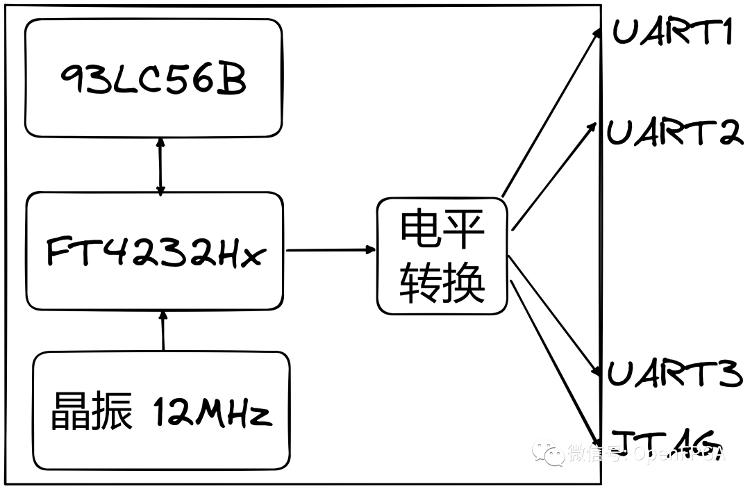
It provides one JTAG and three serial ports.
It supports 7 series + U+ series FPGAs, with level support for 1.5V, 1.8V, 2.5V, and 3.3V, with TCK rates exceeding 30M.
Serial ports 1 and 2 support any TTL level, with selectable 1.8V, 3.3V, and 5V on board, selectable at the position shown in the image below:
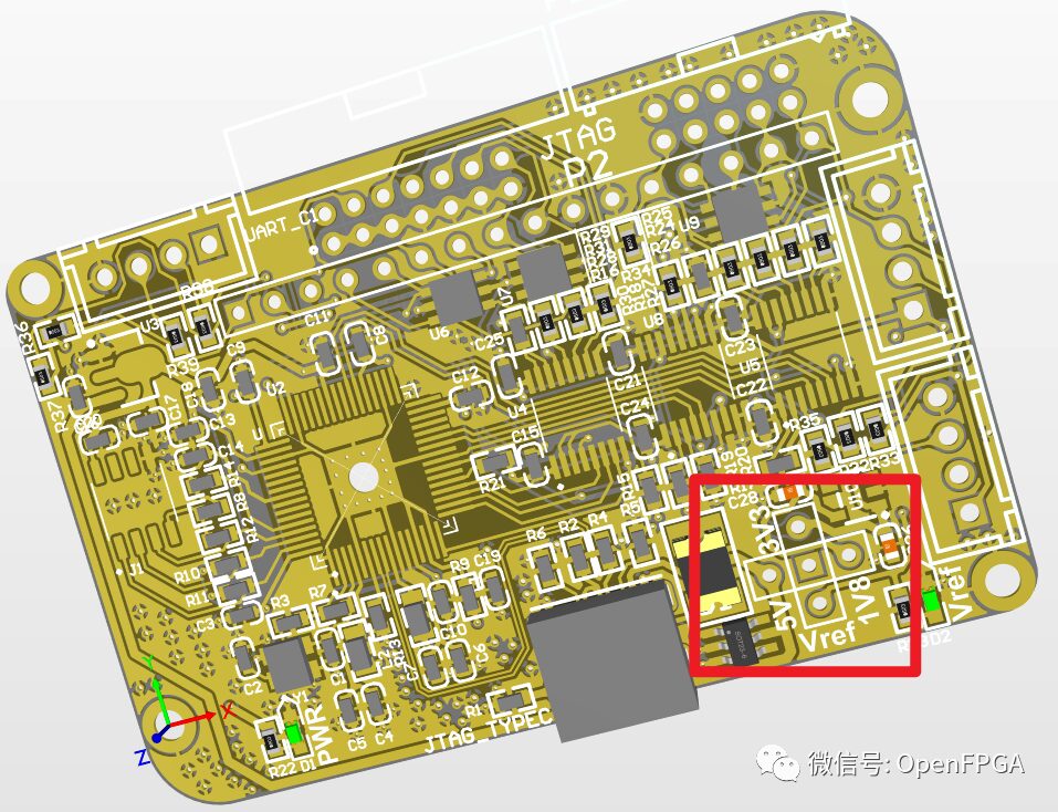
Serial port 3 only supports TTL levels that are the same as the Vref level of JTAG and cannot be set. It can only be used when powered by Vref.
Firmware Programming
It’s very simple; you just need to download the software from the open-source link below:
https://github.com/suisuisi/jtag
Compression password: openfpga
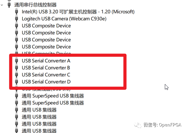
Plug the USB into the computer, and the device manager will display as follows:
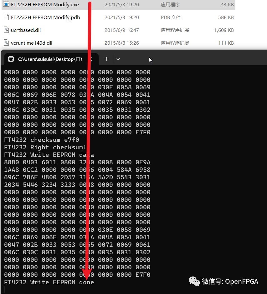
Click the file below to complete the programming.
Expansion Board
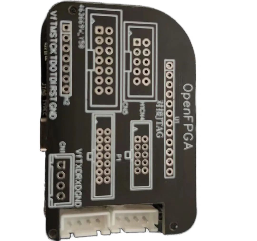
The core board above can be appropriately expanded to add interfaces, compatible with more interface forms. To reduce size, I added an expansion board:
Expansion board address:
https://oshwhub.com/OpenFPGA/jtag-zhuan-jie-ban
Legacy Issues
There are no legacy issues; the main problem is that the TYPE-C connector is too difficult to solder, requiring some skill to manage…
The expansion board needs a hole for a jumper cap to conveniently select the UART level standard; this was not done in the image, but the latest version has been corrected.
Open Source Notice
Software and hardware (schematics, PCBs are all open source). I have tested the board myself, and everyone can modify and produce it themselves.
Lastly, the firmware was obtained from a certain expert and is shared at their request; it is only for learning purposes. Any disputes or issues arising from commercial use are unrelated to this public account and the personnel related to this article~