1. Serial Port Activation Process
Before we start, let’s take a look at a few demo programs for serial ports from different chips.
These include the STM32 V3.5 standard library, the official demo for nRF52832, and the official DEMO for the STC15 series microcontroller with a 51 core.
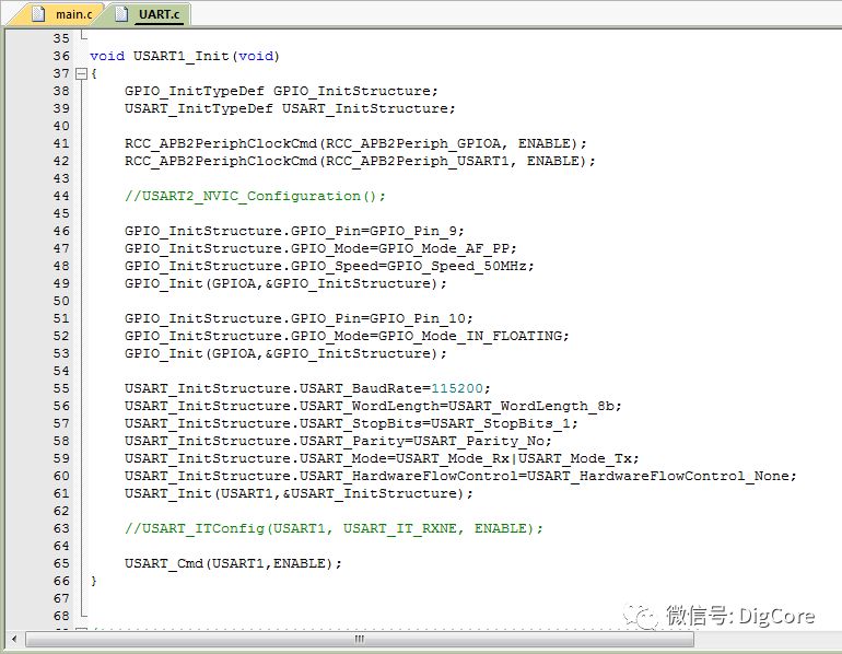
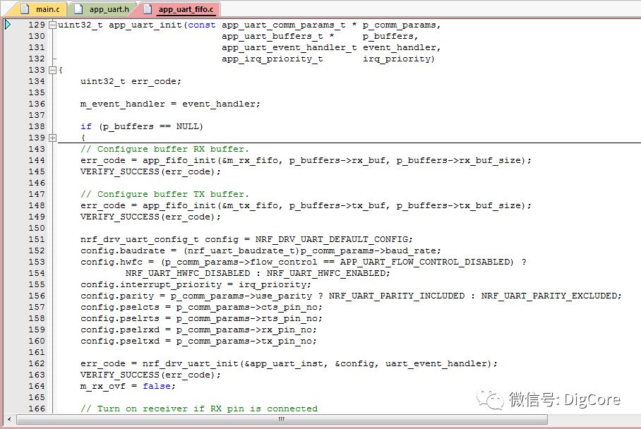
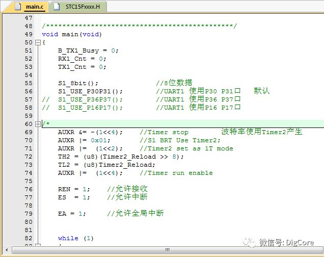
From the above demo examples and the article “Embedded Hardware Communication Interface Protocol-UART (1) Protocol Basics“, we can see that when enabling the serial port, several parameters need to be configured, including baud rate, data bits, parity bits, and stop bits, which can also be reflected in the demo source code.
However, in ARM where pin configuration is flexible, specific configurations for the pins are required.
2. Verifying Input and Output
Once the serial port is initialized, operations can be performed to verify whether the serial port can send and receive data normally.
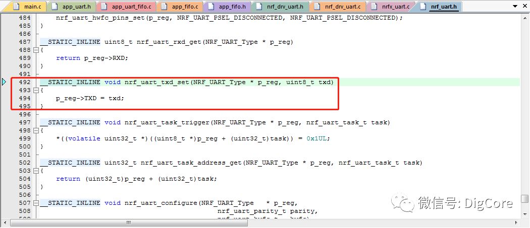
Generally, the most straightforward method is to write data to the output register, which will enable the chip to output UART signals to the corresponding pins.
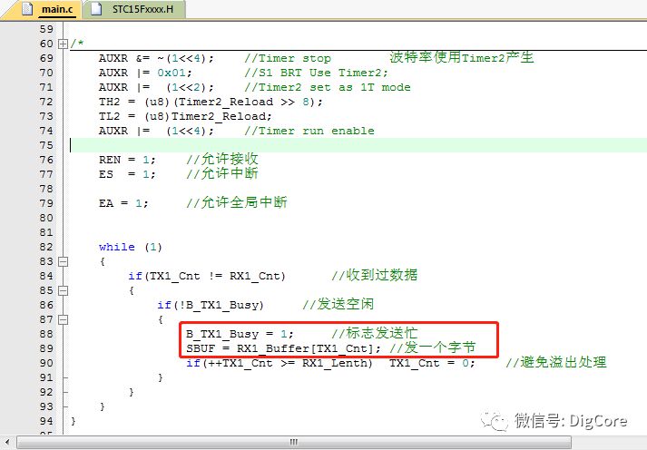
As shown below, we have the STM32 V3.5 standard library, the official demo for nRF52832, and the official DEMO for the STC15 series microcontroller.
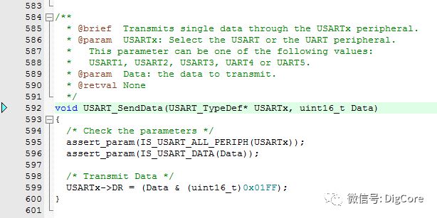
To verify the output of the serial port, after successful initialization, write data to the serial port’s output register while connecting the chip pins with a USB to TTL module, plugging the USB end into the computer’s USB port, and using the computer’s serial assistant software to send and receive data.
3. Debugging–Output
During development and debugging, the output typically includes variable values, code execution positions, algorithm results, and so on. These outputs are only for the debugging phase, while during human-machine debugging, the data output should be easy to read and interpret when using the computer’s serial assistant software for interaction.
1. C Library Function printf Format Output Redirected to Serial Output
During the output of serial port data, data needs to be passed to the register byte by byte, and before transmission, it is essential to place the data and characters to be sent in the same Buffer, then execute polling to transmit until the buffer content is fully transmitted.
This “placing” process also requires some calculations and judgments, especially adding necessary characters to describe the output information, ensuring the information is readable.
The C standard library’s printf function has formatting output capabilities, making it easier to debug the output process using this interface.
This requires redirecting the printf function to the serial output!
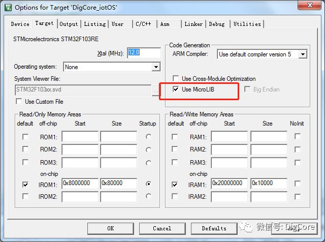
Redirecting can be achieved in just 3 steps:
-
In the Options for target tab, check UseMicroLIB
-
In the serial implementation *.c file, include stdio.h and stdarg.h files
-
Redefine the internal implementation of the int fputc function
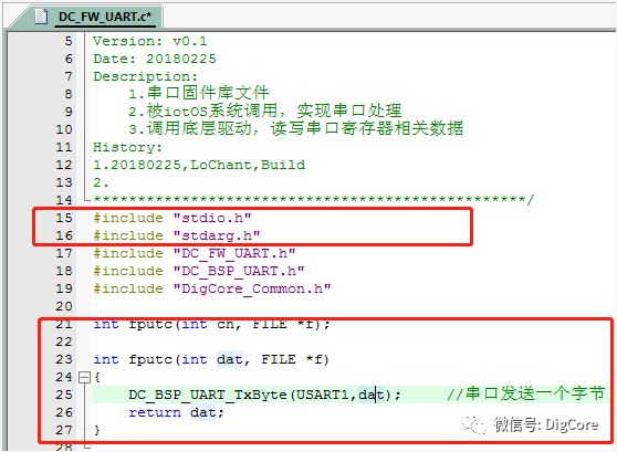
After completing the above 3 steps, you can use the printf function to format output, and it will be received on the serial port.
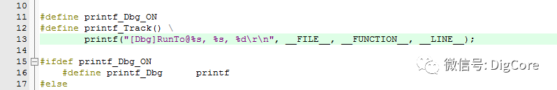
2. ANSI C Standard Predefined Macros:
__LINE__: Line number in the source code (string format)
__FILE__: Filename of the current *.c source file (string format)
__DATE__: Compilation date (string format)
__TIME__: Compilation time (string format)
__STDC__: This identifier is assigned the value 1 when the program strictly adheres to the ANSI C standard;
__cplusplus: This identifier is defined when writing C++ programs.
Having redirected the printf function to the serial port, you can effectively use the serial port for program debugging.
During debugging, you can utilize built-in macros from the ANSI C standard, such as __LINE__ to easily track which line of code is being executed.
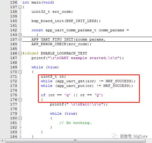
4. Debugging–Input
Serial port reception can be done through polling, interrupts, DMA, and other methods.
The polling method consumes chip resources, making it prone to data loss;
The interrupt method is characterized by quick response and low resource usage;
DMA method varies in configuration across different chips, which can lead to poor code compatibility and portability.
Generally, when analyzing and judging the input data, if using polling, the data can be judged immediately upon receipt; for interrupts and DMA, the data can be stored in a buffer for further analysis and processing.
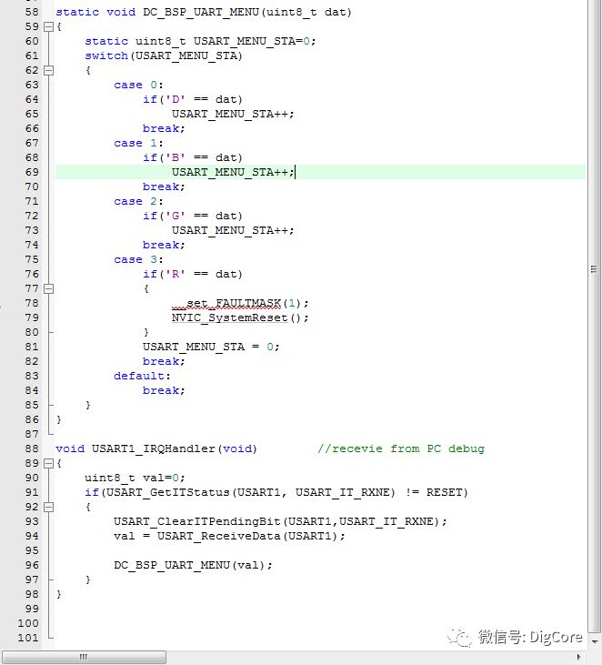
5. Introduction to Data Protocol Parsing
If the command consists of just a few characters, simple judgments as mentioned above can suffice, but in moderately complex engineering projects, such an approach becomes cumbersome for handling and expanding.
For example, if there is a string of data with an uncertain length that may exceed 10, 20, or even 100 bytes, then protocol parsing must be employed.
Typically, data protocols consist of a header, length, checksum, and data content, with data being sent and received in packets; thus, parsing methods are used to analyze the data packets.
This is the widely used “Start Protocol”.
In actual products, there are interfaces for IC/ID card reader modules:
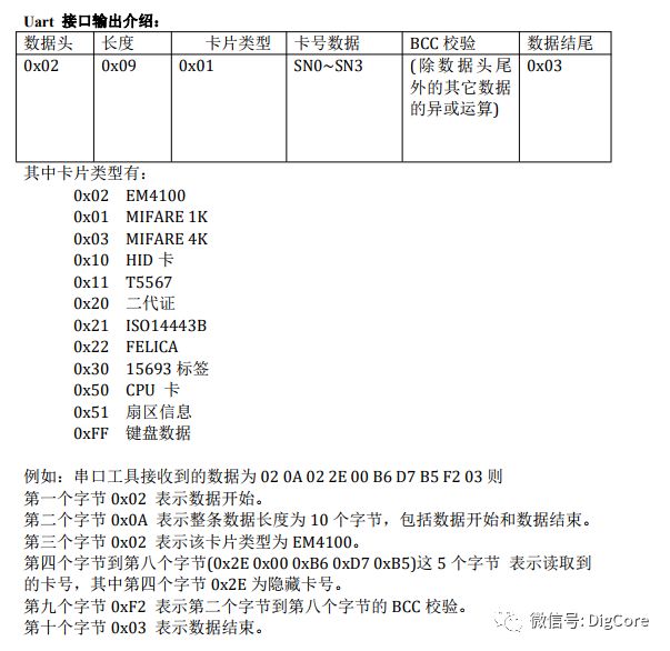
There are also applications in PM2.5 sensors:
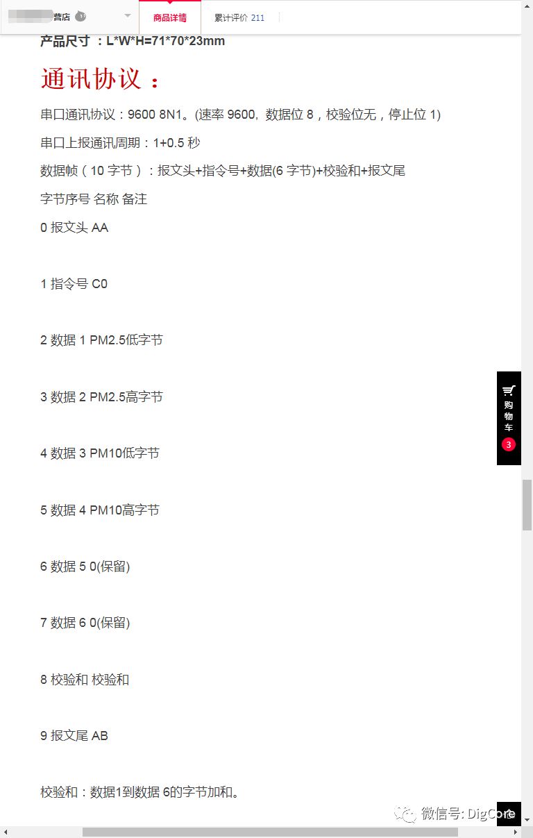
These are all modular products developed for external serial communication, and the data protocol adopts a “Start” frame structure mode.
Stay tuned for more on the design and application of the “Start Protocol” next time!
★★★★★ Recommended Articles:
“Quick Development of MQTT (1) MQTT from an Electronic Engineer’s Perspective”
“Quick Development of MQTT (2) Introduction to MQTT”
“Building an MQTT Client – The Clearest MQTT Protocol Architecture”
“Setting Up an MQTT Server – The Fastest Way to Validate Your Developed Client”
★★★★★ Related Articles
“Embedded Hardware Communication Interface Protocol – UART (1) Protocol Basics”
“Embedded Hardware Communication Interface Protocol – UART (2) Standards under Different Electrical Specifications”