This article will introduce the types and uses of various probes. What is a probe: An oscilloscope is the most commonly used measuring instrument by electronic engineers, and the oscilloscope probe is undoubtedly the most commonly used accessory for the oscilloscope. The oscilloscope probe is the electronic component that connects the measured circuit to the oscilloscope’s input. Without a probe, the oscilloscope becomes just a decoration, serving only as an ornament. Before selecting an oscilloscope probe, it is best to consult the oscilloscope’s manual to understand what kind of probes are suitable for the oscilloscope we are using. The following points are considered important when selecting a probe:
-
Ensure that the probe interface matches the interface of our oscilloscope. Most oscilloscope probe interfaces are BNC interfaces, while some oscilloscopes may use SMA interfaces.
-
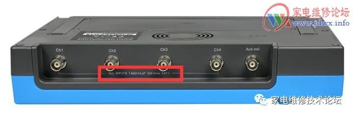
Check whether the input impedance and capacitance of the selected probe match the input impedance and capacitance of the oscilloscope. We all want to minimize the impact of the probe on the measured circuit. The degree of matching between the probe’s impedance and capacitance and that of the oscilloscope greatly affects the accuracy of the measured signal.
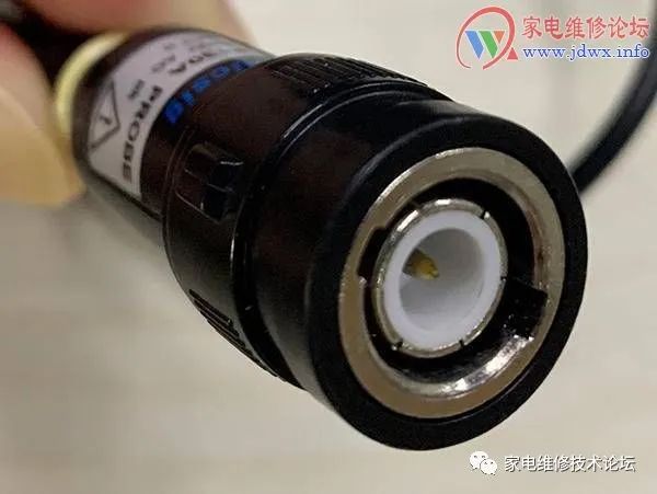
BNC Interface
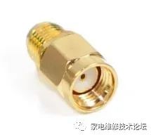
SMA Interface Some oscilloscopes support switching between 50 Ω or 1 MΩ input impedance. However, for most measurements, 1 MΩ is the most common. The 50 Ω input impedance is often used for measuring high-speed signals, such as microwaves, as well as for measuring signal transmission delays in logic circuits and circuit board impedance. The input impedance of the oscilloscope can often be fixed at 1 MΩ or 50 Ω, but the input capacitance of the oscilloscope is affected by bandwidth and other design factors. Generally speaking, the common input capacitance for a 1 MΩ oscilloscope is 14pF. This value may also range from 5pF to 100pF. Therefore, to match the probe to the oscilloscope’s input capacitance, it is important to understand the capacitance range of the probe before selecting it and to adjust the probe’s capacitance using a calibration stick, which is known as probe compensation. This is the first step we should pay attention to when using probes.
So how many probes do we need and what types? Depending on our measurement requirements, the number and types of probes required vary. This is somewhat like a person who plays with a DSLR camera; they may only have one camera but often have many lenses. For example, if we are only measuring DC voltage, a 1 MΩ passive probe is generally sufficient. However, if we need to measure the relative voltage difference between the live wires in a three-phase power supply during power system testing, or between the live wire and neutral (ground) wire, we will need to use a differential probe.
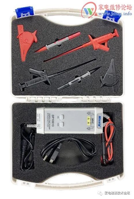
Differential Probe Passive probes are the most common type of probes, and manufacturers usually provide several when purchasing an oscilloscope. Common passive probes consist of the probe head, probe cable, compensation device or other signal conditioning networks, and probe connectors. These types of probes do not use active components like transistors or amplifiers, so they do not require power supply. Generally, passive probes are more common, easier to use, and cheaper. Common passive probes have adjustable attenuation ratios of: 1×: No attenuation 10×: 10 times attenuation 100×: 100 times attenuation 1000×: 1000 times attenuation Passive voltage probes provide various attenuation factors for different voltage ranges. Among these passive probes, the 10× passive voltage probe is the most commonly used. For applications where the signal amplitude is 1V peak-to-peak or lower, a 1× probe may be more suitable, or even essential. In applications with mixed low and medium amplitude signals (tens of millivolts to tens of volts), a switchable 1×/10× probe is much more convenient. However, the switchable 1×/10× probe is essentially two different probes in one, not only differing in attenuation ratio but also in bandwidth, rise time, and impedance (R and C) characteristics. Therefore, these probes cannot fully match the oscilloscope’s input and cannot provide the optimal performance achieved by a standard 10× probe. The probe attenuation is achieved by using internal resistors to expand the oscilloscope’s voltage measurement range, and this internal resistor, when used with the oscilloscope’s input resistance, creates a voltage divider. For example, a typical 10× probe is equipped with an internal 9MΩ resistor, which, when connected to a 1MΩ input impedance oscilloscope, creates a 10:1 attenuation ratio at the oscilloscope’s input channel. This means that the signal displayed on the oscilloscope will be 1/10 of the actual measured signal amplitude, so we often need to set the attenuation ratio to 10X in the oscilloscope’s channel settings.

This attenuation feature allows us to measure signals that exceed the oscilloscope’s voltage limit. Moreover, the attenuation circuit results in a higher resistance (usually a good thing) and lower capacitance, which is important for high-frequency measurements.
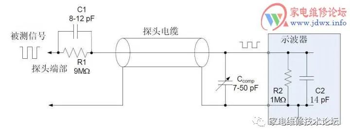
10X Passive Probe Schematic Active Probe Since active probes contain active components like transistors and amplifiers, they require power support, hence the name active probes. In most cases, the active device is a field-effect transistor (FET), which provides very low input capacitance, and low capacitance leads to high input impedance over a wider frequency range. The specified bandwidth of an active FET probe is generally between 500MHz and 4GHz. In addition to having higher bandwidth, the high input impedance of active FET probes allows measurements at test points with unknown impedance, significantly reducing the risk of loading effects. Additionally, the low capacitance reduces ground effects, allowing for longer ground leads. Active FET probes do not have the voltage range limitations of passive probes. The linear dynamic range of active probes is generally between ±0.6V and ±10V.
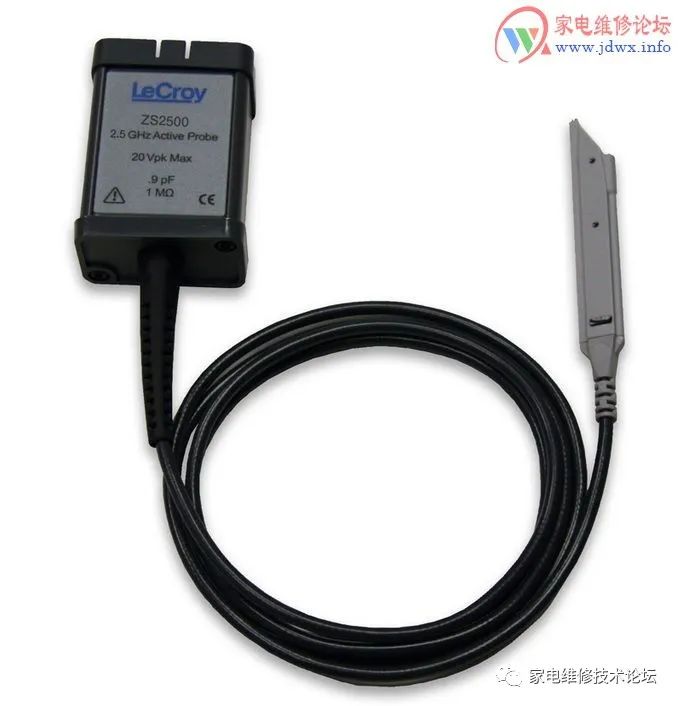
Active Probe Differential Probe The differential probe measures differential signals. Differential signals are referenced to each other rather than to ground. Differential probes can measure signals from floating devices; they essentially consist of two symmetrical voltage probes that are well insulated and have high impedance relative to ground. Differential probes can provide a high common-mode rejection ratio (CMRR) over a wider frequency range. The advantages of differential signals compared to ordinary single-ended signals are most evident in the following three aspects:
-
Strong anti-interference capability: Because the coupling between the two differential lines is good, when there is external noise interference, it is almost simultaneously coupled to both lines, and the receiving end only cares about the difference between the two signals, so the common-mode noise from the outside can be maximally canceled.
-
Effective suppression of EMI: For the same reason, since the two signals have opposite polarities, their electromagnetic fields radiated to the outside can cancel each other out; the tighter the coupling, the less electromagnetic energy is released to the outside.
-
Precise timing positioning: Since the switching changes of differential signals occur at the intersection of the two signals, rather than relying on high and low threshold voltages like ordinary single-ended signals, the impact of process and temperature is reduced, thereby minimizing timing errors and making them more suitable for low-amplitude signal circuits. The currently popular LVDS refers to this type of small amplitude differential signal technology. The principle of differential amplification refers to inputting a pair of signals into an amplification circuit simultaneously and then subtracting them to obtain the original signal. A differential amplifier is constructed using two transistors with identical parameter characteristics, connected in a direct coupling manner. If equal-sized and phase-aligned signals are input at both terminals, the output will be zero, thereby overcoming zero drift.
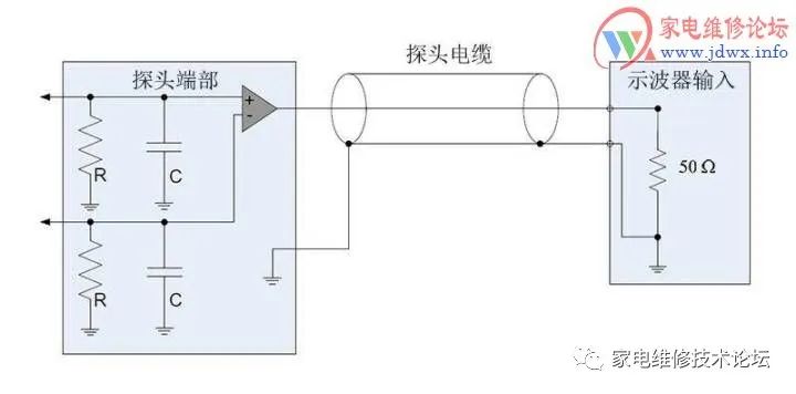
Differential Probe Schematic Current Probe You might wonder why we need a dedicated current probe to measure current when we can easily obtain it by measuring voltage and dividing by the measured resistance. This is because the errors introduced by this method are very significant, and we generally do not use voltage to calculate current. Current probes can accurately measure current waveforms by using current transformers as input, where the signal current magnetic flux is transformed into voltage through a transformer, and then amplified by an internal amplifier before being sent to the oscilloscope. Current probes can be divided into two categories: AC current probes and AC/DC current probes. AC current probes are usually passive probes that do not require external power, while AC/DC current probes are usually active probes. Traditional current probes can only measure AC signals because stable DC current cannot induce current in a transformer. AC current in a transformer generates changes in the electric field with the change in current direction, inducing voltage. However, using the Hall effect, semiconductor devices can produce a voltage corresponding to the DC electric field. Therefore, DC current probes are active devices that require external power.
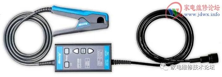
AC/DC Current Probe Finally, here are some suggestions related to probes:
-
Properly compensate the probe: Different oscilloscope input capacitances may vary, and even different channels on the same oscilloscope may have slight differences. To address this, learning to adjust probe compensation is a fundamental skill that engineers should master.
-
When connecting the probe to the measured circuit, the ground terminal of the probe must be connected to the ground line of the measured circuit. Otherwise, in a floating state, the potential difference between the oscilloscope and other devices or the ground may lead to electric shock or damage to the oscilloscope, probe, or other devices.
-
Try to keep the probe’s ground lead close to the point being measured. A long ground lead may cause ringing or overshoot, leading to waveform distortion.
-
When neither of the two test points is at ground potential, a “floating” measurement, also known as differential measurement, should be performed using a specialized differential probe. The probe is crucial for the oscilloscope’s measurements; it must minimize its impact on the circuit being tested and maintain sufficient signal fidelity for the measurements. If the probe alters the signal or changes the way the circuit operates in any manner, the oscilloscope will see a significantly distorted actual signal, potentially leading to erroneous or misleading measurements. From the above introduction, it can be concluded that there are many considerations to keep in mind when selecting and correctly using probes.
Original text: https://www.jdwx.info/thread-798283-1-1.html
Home Appliance Repair Technology Forumjdwx-cn ▲Long press to identify the QR code to follow

Home Appliance Repair Forumjdwxinfo ▲Long press to identify the QR code to follow