Understanding Oscilloscope Probes
The measured signal cannot be directly connected to the oscilloscope, so a device is needed to establish an electrical connection between the test point and the oscilloscope. Depending on the needs, this device can be a simple wire or a more complex circuit. The device responsible for linking the test point and the oscilloscope is the oscilloscope probe. Therefore, oscilloscope probes are crucial; without them, the oscilloscope cannot perform measurements.
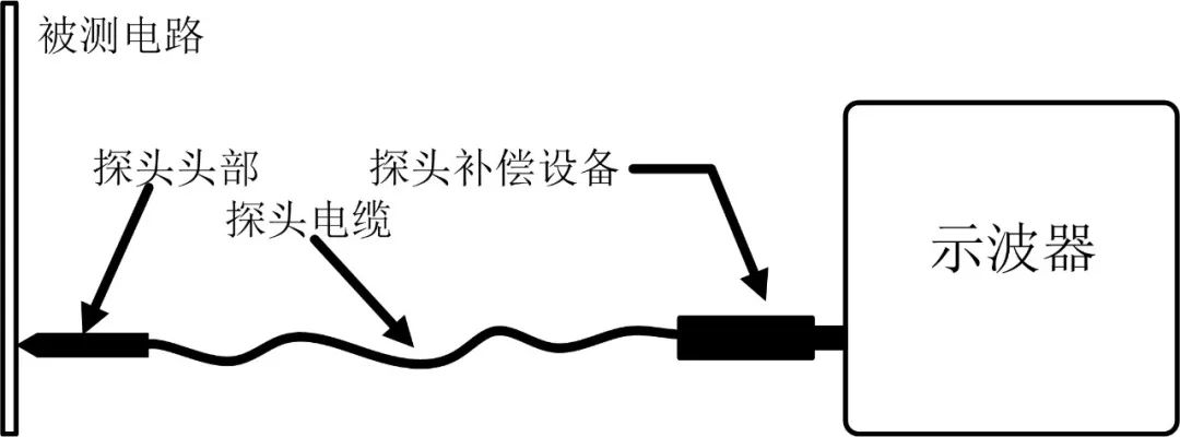
Figure 1
The above diagram illustrates the measurement process with an oscilloscope probe. As shown, an oscilloscope generally has three typical parts: the probe head, the probe cable, and the probe compensation device. The probe head is responsible for direct contact with the test point, thereby establishing an electrical connection with the system under test and ultimately acquiring the signal to be measured. The probe cable allows the oscilloscope and the probe head to remain unaffected by each other, enabling the probe head to be freely moved to make contact with the test point without moving the oscilloscope. Finally, the probe compensation device is mainly used to minimize the negative effects caused by the probe cable, thus maintaining the measurement accuracy of the probe to a certain extent.
From the basic structure of the probe, it can be seen that the probe cannot be considered a transparent device; there will definitely be many performance limitations. For example, the probe cable and compensation device determine the bandwidth of the probe, and the size of the components in the probe also determines the input voltage of the probe. Therefore, the probe will have some basic parameters, which can be summarized as follows:
1. Attenuation Ratio
The attenuation ratio is a parameter that all probes have, indicating the degree to which the probe reduces the signal amplitude. Some probes may have selectable attenuation ratios. Typical attenuation ratios are 1×, 10×, and 100×. A 1× probe means there is no attenuation of the signal. A 10× probe means the signal will be attenuated by a factor of 10 before being input to the oscilloscope. The names 1× and 10× originated because earlier oscilloscopes lacked the ability to automatically identify the probe’s attenuation ratio and adjust accordingly, so these names served as reminders for testers to multiply the measured results by the corresponding factor.
2. Bandwidth
Bandwidth is also an essential parameter for a probe, indicating the frequency point at which the probe causes a -3dB attenuation of the signal. As shown in the following diagram:
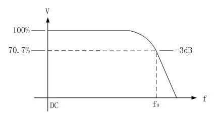
Figure 2
For example, a 100MHz probe has a bandwidth of 100MHz, and a 500MHz probe has a bandwidth of 500MHz. Some probes also have a low-frequency bandwidth specification; for instance, some AC probes cannot transmit DC signals and will have a bandwidth parameter in the low-frequency range. It is worth mentioning that the bandwidth refers to the -3dB spectrum, at which point the amplitude of the measured signal is only 70.7% of the actual signal, so the tester needs to consider whether this result is acceptable; otherwise, a probe with higher bandwidth will be needed.
3. Rise Time
Bandwidth refers to the measurement of a single sine wave. If the signal to be measured is a square wave, the rise time of the probe must be considered. This parameter is the time required for the output signal to rise from 10% to 90% under step signal excitation. This parameter is actually used to assess the error range. For example, if the rise time of the square wave signal being tested is 10ns, then using a probe with a rise time of 3.5ns, the output rise time will be approximately:
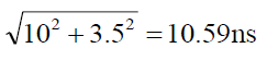
The rise time degrades by 5.9%.
If a 0.7ns probe is used instead, the output rise time will be:
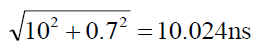
The rise time degrades by only 0.24%. Therefore, when measuring, one should choose a probe with a rise time much smaller than the rise time of the signal being measured, typically needing to be 3-5 times smaller.
4. Maximum Input Voltage
The maximum input voltage refers to the maximum rated voltage that the probe can input. The maximum input voltage depends on the rated breakdown voltage of the probe body and its internal components. This value is generally specified by safety regulations rather than a single voltage; for example, the maximum input voltage for a typical 10× passive probe is 300VRMS CAT II. Here, CAT II refers to a class of testing scenarios, and 300VRMS CAT II indicates the maximum voltage that can be measured in this testing scenario. Moreover, this voltage is not a constant value but varies with frequency. Probes generally provide their voltage rating curves, as shown in the following diagram:
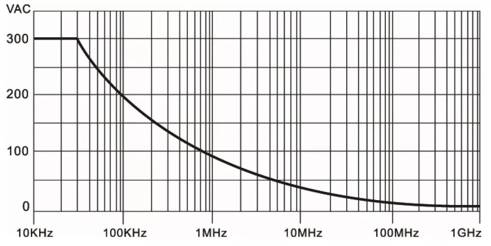
Figure 3
5. Input Capacitance
The input capacitance is the capacitance measured from the probe head end. For active probes, this capacitance includes the parasitic capacitance of the probe tip and the capacitance in the probe’s internal circuit. For some passive probes, it also includes the parasitic capacitance of the probe cable and the capacitance of the oscilloscope itself. The smaller this capacitance value, the higher the frequency that the probe can measure.
6. Input Resistance
The input resistance of the probe is the resistance measured at the probe head end; this value is measured under DC conditions. For passive probes, the greater the attenuation ratio, the higher the probe’s input resistance.
7. Oscilloscope Compensation Range
Most passive probes are universal devices, and there can be differences between different oscilloscopes and even between different channels of the same oscilloscope. To accommodate these differences, probes are equipped with a compensation network to compensate for variations between different oscilloscopes. Insufficient or excessive compensation can lead to measurement errors. This compensation network will have an adjustable range, known as the oscilloscope compensation range. Generally, the oscilloscope compensation range for passive probes is 10-35pF.
8. Cable Length
Every probe must have a probe cable to facilitate measurements. This cable can introduce a certain amount of signal propagation delay. For example, a probe cable of about 1m will introduce approximately 5ns of delay. For a 10MHz signal, this would cause a delay of about 20°. Longer cables will lead to longer phase signal delays. Generally, this delay does not affect measurements because, within a certain bandwidth range, this delay does not change with the signal frequency, thus not causing group delay distortion. Only when measuring with two or more channels simultaneously will transmission delay become significant, especially when voltage probes are used alongside current probes for power measurements, as the delay between different probes can have a substantial impact. Therefore, before measuring, it is necessary to estimate the approximate delay based on cable length. If the delay is too large, the delay calibration function within the oscilloscope should be used.
 Common Types of Probes
The common classifications of probes are shown in the following diagram:
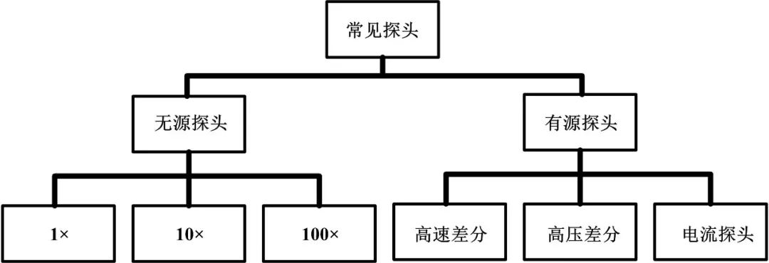
Figure 4 Oscilloscope Probe Classification
Among them, common passive probes include 1×, 10×, and 100× specifications. Generally, a 1× probe is often a low bandwidth probe suitable for measuring low frequency and low voltage signals, while a 100× probe generally has a higher voltage rating, suitable for high voltage measurement scenarios. The bandwidth of a 10× probe is generally quite high, suitable for measuring high-speed signals.
In active probes, high-speed differential probes are suitable for measuring high-speed signals, with very high bandwidth and low loading effects, but they are generally expensive. High-voltage differential probes are generally suitable for testing high voltage situations; compared to passive probes, they not only have higher input voltages (generally over 1000V) but also have very high ground impedance for both measurement lines, allowing for direct non-grounded measurements. For example, when measuring AC mains, the ground line of a passive probe must be connected to the ground of the mains, allowing measurement only between L or N and the ground line, while a high-voltage differential probe can measure between any two lines. Current probes are used to measure current; some current probes can only measure AC, while others can measure both AC and DC.
 Precautions for Using Probes
When using probes, several issues need to be considered:
1. Safety
When using probes for measurements, the most important issue is safety. For example, when using passive probes, the probe’s ground wire is connected to the oscilloscope’s ground. When the oscilloscope is safely grounded, the probe is safe. However, when the oscilloscope is not safely grounded, the probe’s ground wire may have a certain voltage, posing a danger to the user. The specific situation is illustrated in Figure 5:
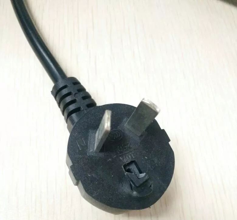
Figure 5
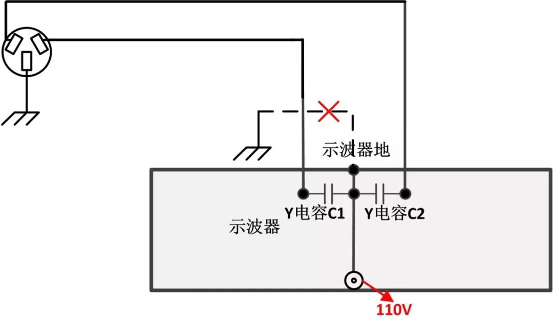
Figure 6 Oscilloscope Grounding
Due to the Y capacitance, the original grounding voltage is not 0V, but half the voltage between L and N, which is 110V. This voltage can be harmful to the human body. Therefore, during measurements with the oscilloscope, it is essential to ensure proper grounding or use an isolation transformer for complete safety; otherwise, there is a risk of electric shock.
Moreover, if the probe’s ground wire is connected to a relatively high voltage, such as the live wire of the mains, it can cause the entire oscilloscope casing to carry 220V high voltage. If a person then touches the oscilloscope, it can result in direct electric shock, which is extremely dangerous, akin to inserting one’s hand into a live electrical outlet.
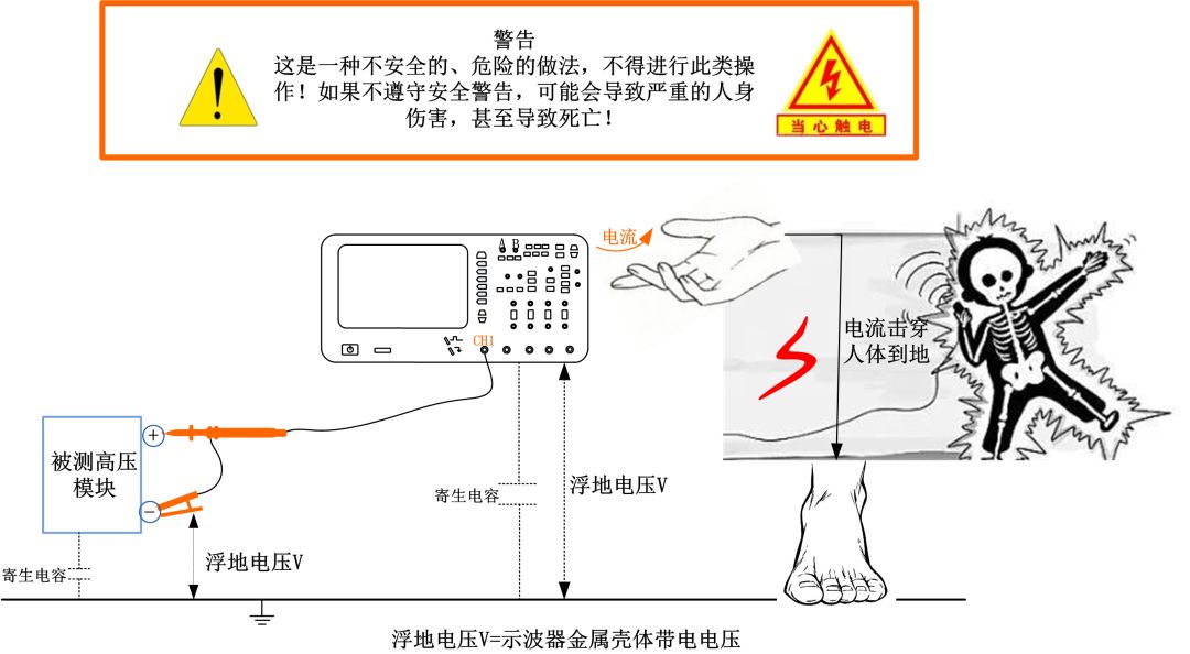
Figure 7
2. Connection Order
The probe is indirectly grounded through the oscilloscope’s power line ground, while the system under test may be a floating system. To avoid danger, the ground wire must be connected to the ground first, grounding the oscilloscope and the system under test together, before connecting the probe tip to the test point. When disconnecting the probe, the probe tip should be disconnected first, followed by the ground wire.
3. Impedance
When using a probe, it is essential to consider the matching issue with the oscilloscope. Common passive probes generally require the oscilloscope’s impedance setting to be 1MΩ. Some active probes require a 50Ω impedance. Before using a probe, check the corresponding impedance specifications in the manual to select the appropriate oscilloscope setting.
4. Bandwidth
When using a probe for measurements, the overall system bandwidth is composed of the probe bandwidth and the oscilloscope bandwidth. Any shortfall in either bandwidth will result in the final measurement not meeting requirements. For example, using a 100M probe with a 500M oscilloscope will yield a maximum bandwidth of only about 100M, thus failing to leverage the 500M oscilloscope’s bandwidth advantage. Therefore, selecting the oscilloscope and probe appropriately is crucial to achieving the desired testing bandwidth.
5. Voltage
When selecting a probe, consider the voltage of the test signal. On one hand, ensure that the test voltage does not exceed the probe’s maximum input voltage; on the other hand, ensure that the probe’s output signal is within the measurable range of the oscilloscope. Testers need to choose probes based on the voltage of the test signal. For example, to measure a 600Vpp voltage signal, a probe with a voltage rating exceeding 600Vpp must be selected, while the maximum measurable voltage for most oscilloscopes is 80V, necessitating a probe with an attenuation ratio greater than 8. Conversely, if measuring a 10mVpp voltage signal, a probe with no attenuation should be used.
6. Ground Wire Effects
Traditionally, the grounding method for oscilloscopes involves using a long ground clip wire. While this grounding method is simple and convenient, it is neither rigorous nor accurate.
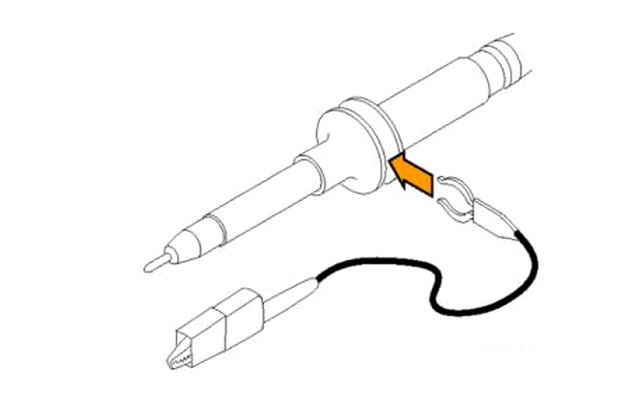
Figure 8 Ground Clip Wire Diagram
Due to the length of the ground clip wire, it will form a parasitic inductance Lgnd. As the length of the clip wire increases, this inductance also increases, and this loop inductance will resonate with the input capacitance Cin of the oscilloscope probe. This results in a non-flat amplitude-frequency characteristic of the oscilloscope, leading to measurement inaccuracies. The following diagram shows the equivalent circuit when using a ground clip.
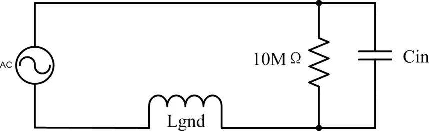
Figure 9 Ground Clip Equivalent Circuit Diagram
The following diagram shows the frequency spectrum characteristic curve simulated using this equivalent circuit:
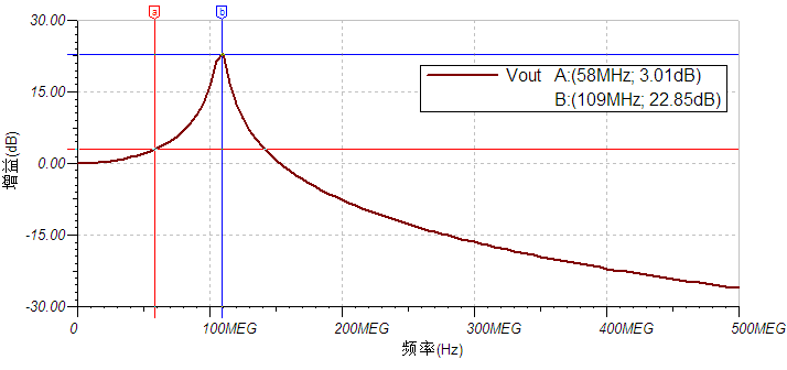
Figure 10 Frequency Spectrum Characteristic Curve
It can be seen that at frequencies above 60MHz, the amplitude has already experienced more than 3dB of overshoot, and around 100M, the overshoot reaches its maximum amplitude. Therefore, using a ground clip for measurements of signals above 60MHz will result in significant distortion. The correct approach should be to use a grounding spring. Grounding springs have very low inductance, which can greatly enhance the probe’s bandwidth.
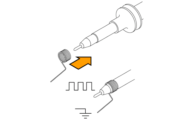
Figure 11 Grounding Spring Diagram
Moreover, using a spring will also reduce the ground loop area, significantly decreasing the radiation interference from noise.
7. Adjustment of Compensation Capacitance
For a 10× passive probe, its equivalent model is shown in the following diagram.
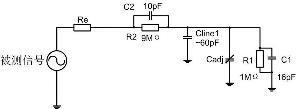
Figure 12 Probe Equivalent Circuit
Where C1 and Cline1 are the parasitic capacitances of the oscilloscope and communication cable, which cannot be removed. Due to R2, a low-pass filter will inevitably be generated, preventing the probe from passing high-frequency signals. To increase the probe’s bandwidth, C2 will be added for compensation.
Calculations yield the system’s zero points:
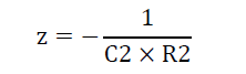
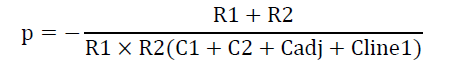
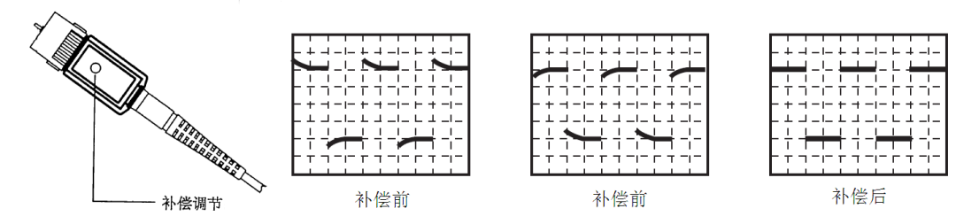
Figure 13 Probe Compensation Diagram
8. Load Effects of Probes
As mentioned earlier, probes have input capacitance and input resistance, meaning they cannot be treated as devices with infinite impedance. The equivalent model during measurement is shown in the following diagram.
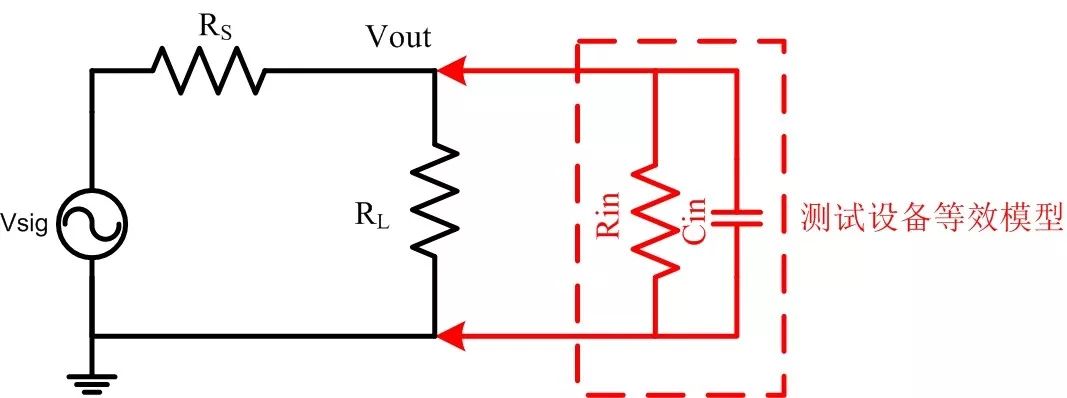
Figure 14
According to circuit knowledge, for DC signals, Vout will decrease compared to before the probe was connected, as the current load is no longer RL but the resistance of RL in parallel with Rin, which will inevitably be less than the original resistance RL. For AC signals, an additional capacitor Cin will be in parallel, creating a new impedance that decreases as frequency increases. This is why sometimes the circuit cannot function properly when the probe is connected. When using probes for measurements, it is necessary to evaluate the load effects of the probe on the system under test. For instance, a typical 1× probe has an input capacitance of about 150pF. If connected to a 50Ω system, it will create a low-pass filter of approximately 40M. If the measured signal is close to or exceeds this frequency, it will cause the system under test to behave abnormally. When performing high-frequency measurements, the smaller the probe’s input capacitance, the less impact it will have on the system.
Summary
Probes are essential in the oscilloscope measurement system. The ZDS4000 oscilloscope boasts excellent performance and comes standard with high-performance passive probes. However, there are many precautions to take when using probes to ensure the oscilloscope’s performance is utilized correctly. Users need to understand these precautions to obtain measurement results safely and accurately.

 If you have any questions, you can:
 Add WeChat ID: zlgmcu-888
 Call ZLG Zhiyuan Electronics Technical Hotline: 400-888-4005.