Abstract: Multi-axis linked equipment frequently experiences synchronization anomalies during normal operation. Through fault diagnosis and data analysis, it is preliminarily determined that the main causes of this anomaly are fluctuations in grid voltage or instantaneous torque fluctuations during the motor’s over-frequency operation.
Introduction
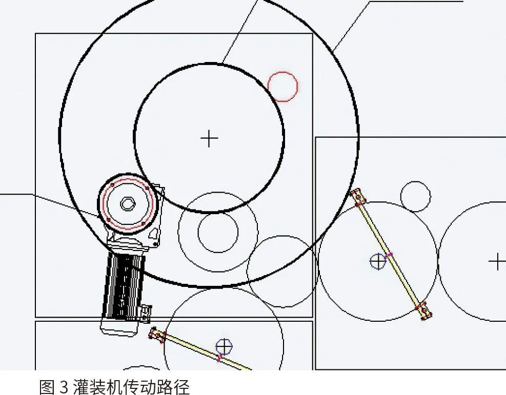
The blow (blow molding machine), fill (filling machine), and cap (capping machine) are three devices that use a star wheel drive as a transitional transmission device to complete the blow molding, filling, and capping of PET (Polyethylene Terephthalate) bottles in one go within a combined machine. The blow-fill-cap equipment produced by Guangzhou Dayilong Company generally operates with two-axis linkage, where the active axis is the main motor of the blow molding machine, and the passive axis is the main motor of the filling machine. Both motors are controlled by Danfoss servo drives to regulate their operating speeds, and synchronization between the capping machine, filling machine, and transitional star wheel is achieved through gear transmission. During operation at Parle Company in India, this equipment frequently encountered synchronization anomalies, leading to severe scratches on the contact areas between the PET bottles and the star wheel, and even causing PET bottles to accumulate between the star wheel and its protective plate, resulting in deformation of the mold support pillars. The customer has strongly reacted to this fault and requested the company to resolve the issue.
1. On-Site Diagnosis
1.1 Mechanical Transmission Diagnosis
After the mechanical and electrical engineers dispatched by the company arrived on-site, they stopped the machine to observe and adjust the mechanical transmission parts and gear gaps. They also rechecked the locking torque of the potentially loose gear locking screws. The equipment was then operated in single-axis mode for about 30 minutes, and no synchronization anomalies caused by gears or other mechanical issues were found. It was preliminarily judged that this fault was not caused by mechanical transmission errors.
1.2 Test Run
After single machine operation, the two-axis linkage was run under no-load conditions. A high-speed camera was used to capture the transition positions between the blow molding machine and the filling machine at the two transitional star wheels, running continuously for 15 minutes without any synchronization anomalies observed. Subsequently, a 15-minute simulated production run was conducted, during which it was found that bottles were scratched at the contact points with the star wheel, leading to a preliminary judgment that the scratches were caused by two-axis synchronization errors.
1.3 Servo Parameter Inspection
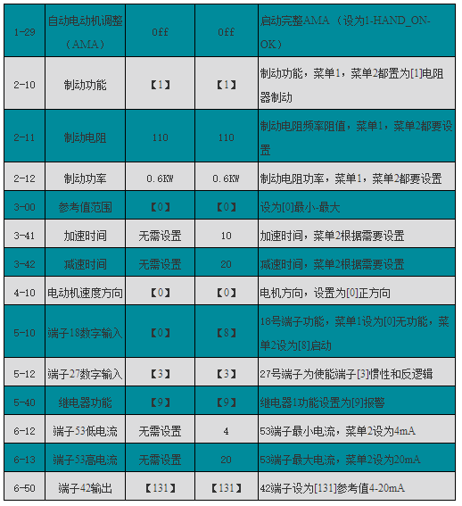
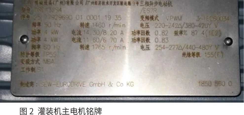
After restoring all servo parameters to factory settings and reconfiguring relevant parameters, synchronization anomalies still occurred during the subsequent test production, leading to a preliminary judgment that this synchronization anomaly was unrelated to the servo parameter settings. However, during the operation after parameter settings, it was found that the operating frequency of the filling machine was 58.7Hz, while the motor nameplate indicated a rated voltage and frequency of 380V/50Hz, meaning the actual operating frequency exceeded the rated frequency by 8.7Hz.
Table 1 Servo Parameters of the Filling Machine
2. Motor Characteristic Analysis
2.1 The Impact of Grid Voltage on Motor Output Torque
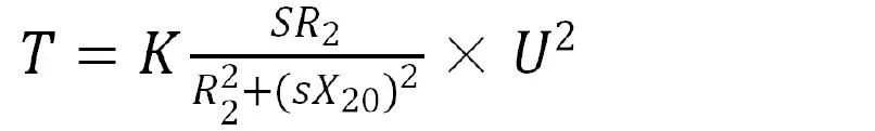
According to the formula relating the maximum output torque of the motor to voltage:
 (1)
(1)
Where: U is the input voltage; R2 is the resistance of each phase of the rotor winding; X20 is the reactance of each phase of the rotor winding when the motor is stationary; K is the motor structure constant; s is the slip rate.
From the above formula, it can be seen that the maximum output powerTmax is proportional to the square of the voltage, thus the system is very sensitive to voltage fluctuations. Based on our years of experience in project commissioning in India, the grid voltage across the country is extremely unstable. Similar situations have occurred in previous projects where equipment experienced abnormal heating and flow fluctuations due to unstable grid voltage. After requiring the customer to monitor the grid voltage, the customer reported monitoring results indicating that the voltage indeed dropped below the rated voltage by10% (around340V).
2.2 The Impact of Maximum Motor Output Power on Output Torque
After eliminating various factors that could affect the synchronization of the blow-fill-cap system, the on-site engineers considered the motor’s over-frequency operation at the design speed and thus needed to analyze the motor’s characteristics in this operating environment.
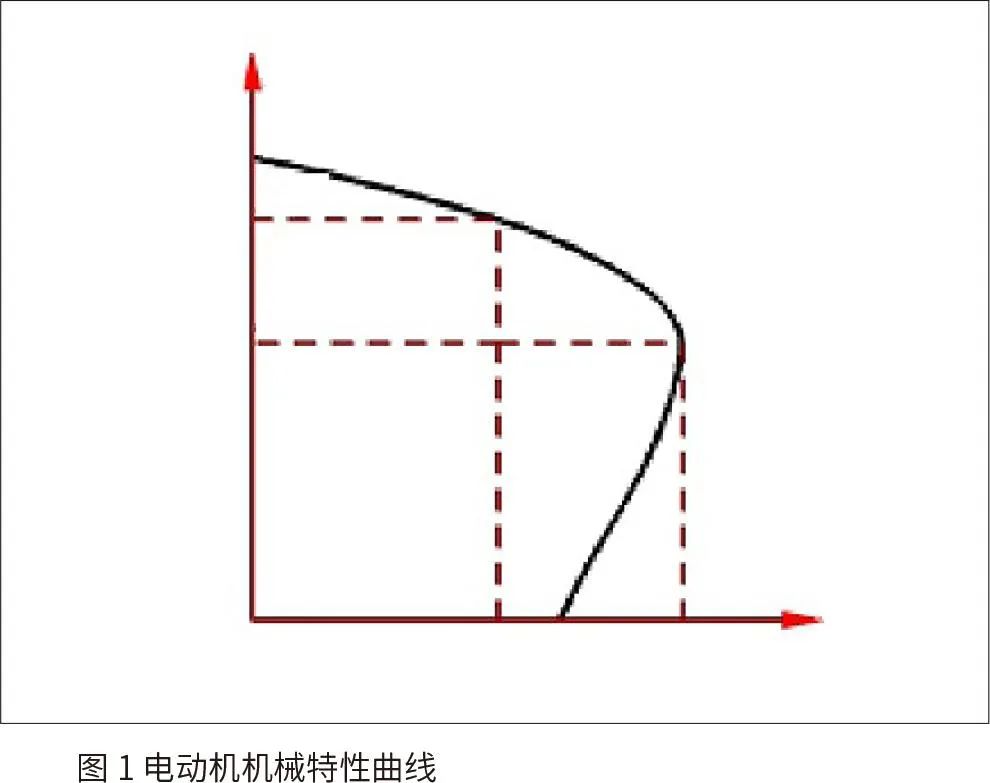
According to the mechanical characteristic curve of the motor, its electromagnetic torque automatically adjusts with changes in load. This process is described asTL (load torque)↑→n (speed)↓→ s (slip rate)↑→I (current)↑→T (output torque)↑, meaning that when the load increases, the speed decreases, which in turn increases the slip rate. At this point, the current increases, causing the motor output power to rise, and the system reaches a new equilibrium. However, when the load resistance torque of the filling machine reaches the maximum output torque of the motor, the motor may slow down. If this load cannot automatically decrease to the motor’s maximum output torque, the motor will be forced to stop.
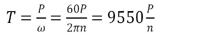
According to the formula for mechanical power of rotating bodies:
 (2)
(2)
Where: T is torque; P is output power; ω is angular speed; n is speed,
From formula 1, it can be seen that for a motor with a certain output power, the higher the speed, the smaller the output torque. According to calculations, the filling machine selected a reduction motor, which, when operating at the rated frequency, has an output speed of 18r/Min, corresponding to a capacity of 25920BPH (Bottles Per Hour). However, the contractual capacity of this equipment is 26400BPH. To achieve this capacity, theoretically, the inverter must over-frequency by 22%, which means 61Hz to reach the contractual output. However, increasing the servo output frequency to enhance the filling machine’s operating speed will reduce the corresponding motor output torque. Therefore, under over-frequency operation, it is highly likely that the filling machine’s main drive motor will not have enough output torque to accurately follow the speed of the blow molding machine, leading to synchronization anomalies.
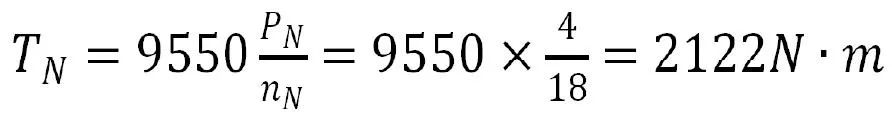
Calculating the rated output torque of the motor at the rated frequency:
 (3)
(3)
Where:TN is the rated torque (output torque for a capacity of25920BPH); PN is the rated power; nN is the rated output speed of the reduction motor.
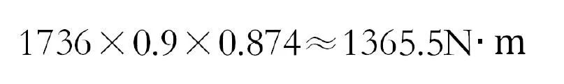
Multiplying by the mechanical efficiency of the reducer (87.4%) and the gear transmission efficiency of the first stage of the filling machine (90%), it can be seen that the actual torque obtained by the filling machine is:
 (4)
(4)
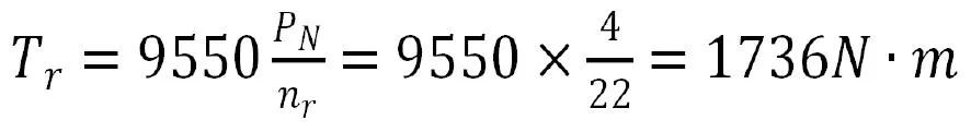
Since the designed capacity of this machine is 26400BPH, according to the inherent mechanical structure, the output of the reduction motor needs to reach 22r/Min, at this time, the motor’s rated torque is:
 (5)
(5)
Where,Tr and nr correspond to the motor output torque and speed when the equipment capacity is26400BPH. Similarly, the actual torque obtained by the filling machine is:
 (6)
(6)
According to the mechanical structure of the filling machine, it has 50 filling valves, and the filling machine speed is 8.8 revolutions/minute, with a rotating part mass of approximately 2620Kg and a rotating body diameter of 1900mm, when the output is 26400BPH.
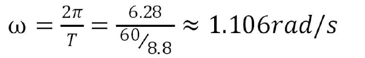 (7)
(7)
Where: ω is angular speed; T is the period.
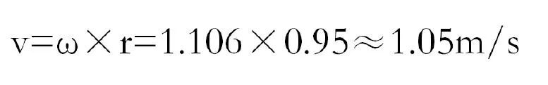 (8)
(8)
Where: v is linear speed; r is the radius of the filling machine’s rotating body.
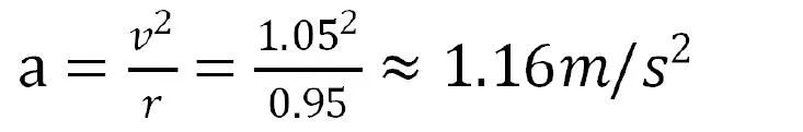
 (9)
(9)
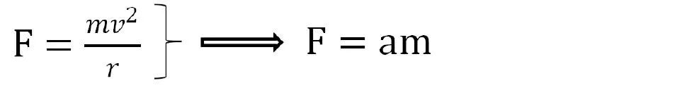
Where: F is the centripetal force acting on the rotating body; a is acceleration, v is linear speed.
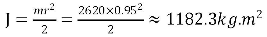 (10)
(10)
Where: J is the moment of inertia, m is the mass of the rotating body (filling machine), r is the radius of the filling machine.
Thus, the torque of the filling machine can be derived:
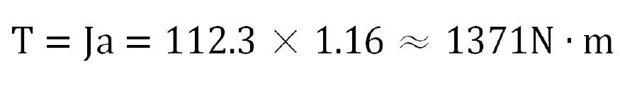 (11)
(11)
TN >T >Tr, the mechanical required driving torque is between the torque generated by the motor at26400BPH and25920BPH, thus it is possible that the driving torque is too small, leading to synchronization anomalies in the equipment.
3. Conclusion
Based on the above on-site inspection results and analysis of motor characteristics, a preliminary solution to this fault has been reached with the customer: first, install a voltage stabilizer to ensure that the grid voltage remains stable within 380V±10%; second, as an alternative solution, if synchronization anomalies still occur under stable voltage conditions, the reduction motor will be replaced to increase its output power.
Wu Yangyou/Guangzhou Dayilong Packaging Machinery Co., Ltd.