A logic analyzer is an instrument used to analyze the logical relationships in digital systems. It belongs to the category of data domain testing instruments and is a type of bus analyzer, meaning it is based on the concept of buses (multiple lines) and can observe and test data flows across multiple data lines. This instrument is very effective for testing and analyzing complex digital systems. A logic analyzer collects and displays digital signals from the test device using a clock, with the primary function being timing determination. Unlike oscilloscopes, which display multiple voltage levels, a logic analyzer typically displays only two voltages (logic 1 and 0). After setting a reference voltage, the logic analyzer determines the measured signal using a comparator: signals above the reference voltage are classified as High, and those below are classified as Low, forming a digital waveform between High and Low.
The operation of a logic analyzer involves data collection, storage, triggering, and display. Because it uses digital storage technology, it can separate the data collection and display processes, or they can occur simultaneously. When necessary, the stored data can be displayed repeatedly for easier analysis and research.
To measure a system, connect it to the logic analyzer and use its probes (which cluster several probes together with fine tips for probing high-density integrated circuits) to monitor the data flow of the tested system, forming parallel data sent to the comparator. The input signal is compared to an externally set threshold level in the comparator. Signals greater than the threshold output a high level on the corresponding line, while signals lower than the threshold output a low level, shaping the input waveform. The shaped signals are sent to the sampler, where sampling occurs under the control of clock pulses. The sampled signals are stored sequentially in memory. The sampling information is organized in a ‘first in, first out’ manner in memory, and upon receiving a display command, the information is read out in order and displayed according to the set display method.
Has enough input channels
Offers various flexible triggering methods to ensure accurate positioning of the observed data flow (for software, it can track any program segment running in the system, and for hardware, it can detect and display glitches).
Has memory functions to observe single and non-periodic data information and diagnose random faults.
Has delay capabilities for analyzing the causes of faults.
Has filtering functions to select desired data and remove irrelevant data.
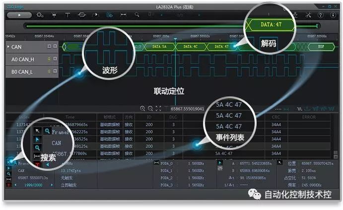
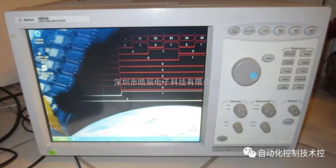
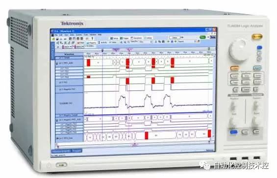
Offers multiple display methods, allowing for character, mnemonic, and assembly language program displays, and displaying data in binary, octal, decimal, and hexadecimal formats, as well as timing diagrams showing the timing relationships between information.
Can drive time-domain instruments to reproduce the real waveform of the signal being tested and assist in fault location.
Has reliable glitch detection capabilities.
An oscilloscope converts electrical signals into visible images, making it easier to study the changes in various electrical phenomena. It can observe different signal amplitudes over time and test various electrical quantities, such as voltage, current, frequency, phase difference, modulation depth, etc. A logic analyzer, on the other hand, collects and displays digital signals from the test device using a clock, focusing primarily on timing determination. Unlike oscilloscopes, which can display many voltage levels, a logic analyzer typically displays only two voltages (logic 1 and 0). After setting a reference voltage, the logic analyzer determines the measured signal using a comparator: signals above the reference voltage are classified as High, and those below are classified as Low, forming a digital waveform between High and Low. Although some oscilloscopes now have logic functions to meet some needs, they are still relatively low-end compared to logic analyzers, which can have over 100 channels with high sampling rates and frequencies. The distinction between the two instruments is significant: logic analyzers are used for timing analysis, while oscilloscopes are primarily used to observe the shape of electrical waveforms.
Functional simulation only cares about whether the logical relationships between outputs and inputs are correct, without considering timing delay information. For example, if input a passes through an inverter to output b, functional simulation will show that when a changes from 0 to 1 at time t1, b will change from 1 to 0 at the same time t1. The changes in output and input occur simultaneously, reflecting the ‘NOT’ logic. Timing simulation, however, not only reflects the logical relationships between outputs and inputs but also calculates timing delay information, making it closer to actual system behavior. For instance, if input a passes through an inverter to output b, timing simulation will show that when a changes from 0 to 1 at time t1, b will change from 1 to 0 at a later time t2, where t2 > t1, and the difference t2-t1 represents the delay of the inverter. The simulation results reflect not only the ‘NOT’ logic but also the timing delay of the NOT gate. However, it should be noted that this timing delay is an ‘estimated’ result from the simulation.