1. Introduction
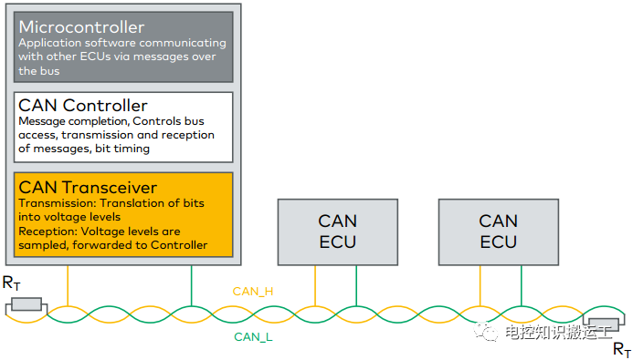
The CAN bus was developed by the German company BOSCH, with a maximum speed of up to 1Mbps. The fault tolerance of CAN is particularly strong, and the CAN controller has a powerful error detection and handling mechanism built-in.
Additionally, unlike traditional networks (such as USB or Ethernet), CAN nodes do not transmit large data blocks between each other. A single CAN message can carry a maximum of 8 bytes of user data, and the use of short packets allows the system to achieve better stability. The CAN bus has a bus arbitration mechanism, allowing for the establishment of multi-master systems.
2. CAN Standards
CAN is a serial communication bus defined by an international standards organization. Initially used in the automotive industry, it replaces the complex wiring in vehicles with two signal buses. The CAN bus features high anti-interference capabilities, self-diagnosis, and data error detection functions, making it widely used in various industrial applications, including building automation, medical, and manufacturing industries.
The CAN communication protocol ISO-11898:2003 standard describes how information is transmitted between devices on the network, as well as which layers conform to the Open Systems Interconnection (OSI) reference model. Actual communication occurs in the physical medium connecting the devices, with the characteristics of the physical medium defined by the physical layer in the model. The ISO11898 architecture defines seven layers, with the lowest two layers in the OSI model serving as the data link layer and physical layer, as shown in Figure 2-1.
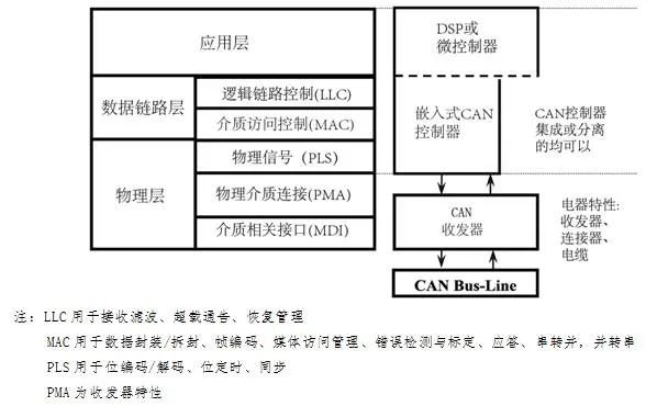
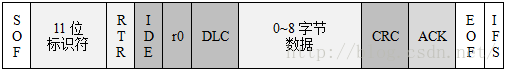
Figure 3-1: Standard CAN – 11-bit Identifier
· SOF – Frame start, dominant (logical 0) indicates the start of the message and is used to synchronize nodes on the bus.
· Identifier – Standard CAN has an 11-bit identifier used to determine the message priority. The smaller the value of this field, the higher the priority.
· RTR – Remote transmission request bit, when information is needed from another node, this bit is dominant (logical 0). All nodes can receive this request, but the frame identifier determines the designated node. The response data frame is also received by all nodes and can be used by interested nodes.
· IDE – The identifier extension bit being dominant indicates this is a standard CAN format; being recessive indicates this is an extended CAN format.
· r0 – Reserved bit (may be used in future standard revisions)
· DLC – 4-bit data length code indicating the number of bytes of data being transmitted; a single CAN frame can carry a maximum of 8 bytes of user data.
· Data0~8 – A maximum of 8 bytes of user data can be transmitted.
· CRC – 16-bit (including 1-bit delimiter) CRC checksum used to check the transmission data segment preceding the user data area (including the data area).
· ACK – 2 bits, including the acknowledgment bit and acknowledgment delimiter. In the sending node’s message frame, the ACK bits are recessive; when the receiver correctly receives a valid message, it sends a dominant bit back to the sending node during the acknowledgment period, indicating acknowledgment. If the receiver finds an error in this frame of data, it does not send an ACK acknowledgment to the sending node, which will then retransmit this frame of data later.
· EOF – 7-bit frame end flag, all recessive bits. If any of these 7 bits appear dominant, it will cause a bit stuffing error.
· IFS – 7-bit inter-frame spacing flag; the CAN controller requires some time to correctly place the received frames into the message buffer, and the inter-frame spacing provides this time.
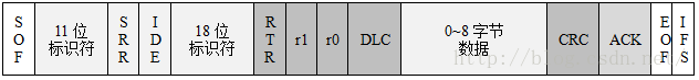
· SRR – Replaces the remote request bit and is recessive. Therefore, when standard frames and extended frames conflict and the basic identifier of the extended frame matches the identifier of the standard frame, the standard frame has a higher priority than the extended frame.
· IDE – The recessive bit indicates the flag for the extended frame, with the 18-bit extended identifier following the IDE bit.
· r1 – Reserved
Click the mini-program below to see more maintenance cases