The oscilloscope is one of the most important testing instruments in modern electronics, and its applications are also very broad in other fields. The main use of an oscilloscope is to observe and measure the waveforms of electrical signals. Additionally, using its image display function, users can directly measure parameters such as the amplitude, frequency, phase, and pulse width of electrical signals. There are many types and models of oscilloscopes, each with different uses and characteristics. Generally, they can be divided into general-purpose oscilloscopes, multi-channel oscilloscopes, logic oscilloscopes, and dedicated oscilloscopes. Below, we will use the DS1022C digital oscilloscope as an example to introduce its usage methods.
1Function Overview
1. The DS1022C digital oscilloscope combines ease of use, excellent technical specifications, and numerous functional features to help users complete their tasks more quickly.
2. The DS1022C digital oscilloscope provides users with a simple and clearly functional front panel for all basic operations. The scale and position knobs for each channel allow for intuitive operation, and to speed up adjustments for easier measurements, users can directly press the (AUTO) button to immediately obtain suitable waveform display and range settings.
3. The DS1022C digital oscilloscope also has high-performance specifications and powerful features needed to complete measurement tasks more quickly.
4. Performance features of the DS1022C digital oscilloscope.
(1) Dual analog channels with multi-channel bandwidth;
(2) Sixteen digital channels that can be independently turned on or off, or turned on or off in groups of eight (mixed-signal oscilloscope);
(3) High-resolution color LCD display system with 320×234 resolution;
(4) Supports plug-and-play USB storage devices and printers, and can be upgraded via USB storage devices;
(5) Adjustable waveform brightness for analog channels;
(6) Automatic waveform and status settings (AUTO);
(7) Storage of waveforms, settings, CSV, and bitmap files, as well as waveform and settings reproduction;
(8) Fine delay scan function that easily balances waveform details and overview;
(9) Automatic measurement of 20 waveform parameters;
(10) Automatic cursor tracking measurement function;
(11) Unique waveform recording and playback function;
(12) Supports quick calibration functions for the oscilloscope;
(13) Built-in FFT;
(14) Practical digital filters, including LPF, HPF, BPF, BRF;
(15) Pass/Fail detection function with opto-isolated Pass/Fail output port;
(16) Multiple waveform mathematical operation functions;
(17) Unique adjustable trigger sensitivity to meet special measurement requirements in different situations;
(18) Multi-language menu display;
(19) Pop-up menu display for more convenient and intuitive user operation;
(20) Display of help information in both Chinese and English;
(21) Supports input in both Chinese and English.
2Panel Introduction
The DS1002C provides users with a simple and clearly functional front panel (as shown in Figure 1) for basic operations. The panel includes knobs and function keys. A column of five gray buttons on the right side of the display screen serves as menu operation keys (defined from top to bottom as numbers 1 to 5). Through these, users can set different options in the current menu, while the other keys are function keys that allow users to enter different functional menus or directly access specific functional applications.
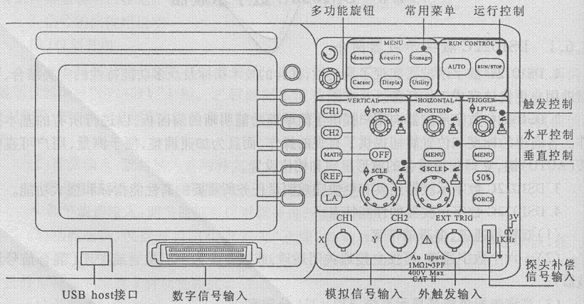
Figure 1: Front Panel of the DS1002C Digital Oscilloscope
3Function Check Operation
Perform a quick function check to verify that the instrument is operating correctly.
1. Turn on the instrument power.
After powering on, the instrument performs all self-check items and confirms passing the self-check. Press the STORAGE button, then use the menu operation keys to select “Storage Type” from the top menu box, and then bring up the “Factory Settings” menu box.
2. Connect the oscilloscope to the signal.
Follow these steps to connect the signal:
(1) Use the oscilloscope probe to connect the signal to Channel 1 (CH1): Set the probe switch to 10X, connect the oscilloscope probe to Channel 1, align the probe connector with CH1 and insert it into the coaxial cable connector (BNC), then turn it to the right to tighten the probe, as shown in Figure 2.
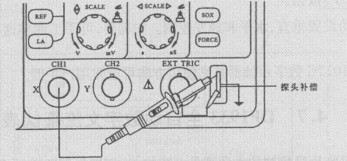
Figure 2: Step (1)
(2) The oscilloscope needs to input the probe attenuation factor. This attenuation factor changes the vertical range scaling of the instrument, allowing the measurement results to correctly reflect the signal level being measured. The method is as follows: Press the “CH1” function key to display Channel 1’s operation menu, and use the 3rd menu operation key parallel to the probe item to select the attenuation factor corresponding to the probe being used. The setting should be 10X, as shown in Figure 3.
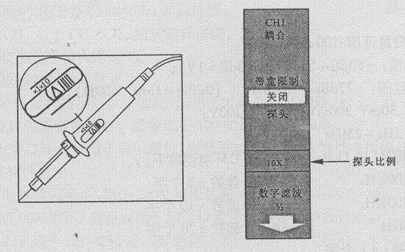
Figure 3: Step (2)
(3) Connect the probe tip and ground clip to the probe compensator connector. Press the “AUTO” (automatic setting) button, and within a few seconds, a square wave will display (1KHz: about 3V peak-to-peak). If this square wave does not display correctly, the probe compensation capacitor needs to be adjusted to correctly display this standard test signal.
(4) Check Channel 2 (CH2) in the same way. After pressing the “OFF” function key, press (CH2) to turn off the channel, then press (CH2) to turn on Channel 2, and repeat Steps (2) and (3).
4Automatic Setting of Waveform Display
The DS1022C digital oscilloscope has an automatic setting function. According to the input signal, it can automatically adjust the voltage scale, time base, and trigger mode to achieve the best waveform display. The automatic setting requires that the frequency of the measured signal is greater than or equal to 50Hz and the duty cycle is greater than 1%.
The operation steps for using the automatic setting are as follows:
1. Connect the measured signal to the signal input channel (such as the FM or AM signal from a radio);
2. Press the “AUTO” button. The oscilloscope will automatically set the vertical, horizontal, and trigger controls. If necessary, manual adjustments can be made to these controls to achieve the desired waveform display.