The oscilloscope is one of the most versatile tools in the toolbox of electronic engineers and enthusiasts. It converts voltage signals into waveforms that change over time, allowing users to observe related information such as signal frequency, amplitude, and noise.
Modern Oscilloscopes
Almost all application electronics, electrical laboratories, or workbenches have an oscilloscope, and many people take its existence for granted. However, the birth of the oscilloscope is quite fascinating, involving many accidental discoveries and unusual observations.
Compared to sound and light signals, electromagnetic signals cannot be directly perceived by humans. Understanding how to describe and detect these signals is fundamental to further exploring electromagnetic phenomena. So, what processes has it undergone? Next time you see a clear and smooth sine waveform displayed on the oscilloscope screen, you can marvel at the history of the oscilloscope’s development.
Amber and Magnet
In early human understanding of electricity and magnetism, people perceived these phenomena through the attraction of amber and magnets to small insulating objects or iron materials. At that time, electricity and magnetism were considered two unrelated physical phenomena.
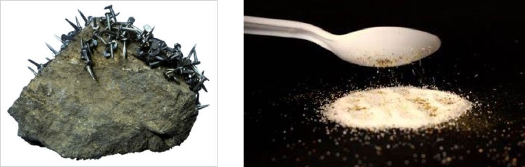
(Left) Magnet attracts iron; (Right) A plastic spoon with static electricity attracts powder
This method can only qualitatively measure whether electromagnetic signals exist and cannot accurately quantify the relationship of the signals.
Frog Galvanoscope
In 1771, Italian physicist and physiologist Galvani discovered that when his assistant touched the sciatic nerve of a frog’s thigh with a metal scalpel, the frog’s leg would twitch, revealing that electrical stimulation could cause movement in biological tissues.
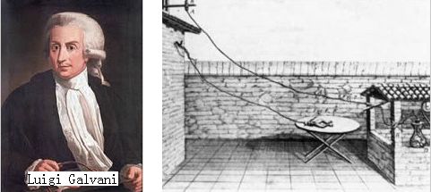
Galvani’s frog leg experiment schematic
His discovery caught the interest of Italian physicist Alessandro Volta twenty years later, in 1791. Building on this, he found that using two different metals to touch the frog’s leg would also cause an electrical phenomenon and further replaced the frog’s leg with other electrolytes to create a chemical battery.
Galvani’s frog leg testing method was so sensitive that it continued to be used even after the invention of mechanical galvanometers in 1820. However, its production and maintenance were complicated, and it could only indicate whether there was current, without showing the direction of the current.
Hand-drawn Current Signal Waveforms
(Oscillograms)
Electromechanical devices like galvanometers were used to display current information more accurately and conveniently than frog legs, and galvanometers with mirrors could achieve very high sensitivity.
By observing the deflection angle of the galvanometer, one could manually draw the current signal waveform. However, this process was very cumbersome and time-consuming.

(Left) Mechanical galvanometer; (Right) Galvanometer with mirror
French scientist Jules Francois Joubert invented a mechanical device that could replace the manual drawing of current waveforms, automatically plotting the signal waveforms based on the galvanometer’s deflection angle.
In 1917, Joubert invented the automatic waveform plotting device
Automatic Waveform Plotter
(Electromechanical Oscillographs)
The first true fully automatic current signal plotting device was invented by French engineer Hospitalier in 1902, known as the Hospitalier waveform recorder (Ondograph). This device drew signal waveforms by driving a pencil on paper rolled over a drum.
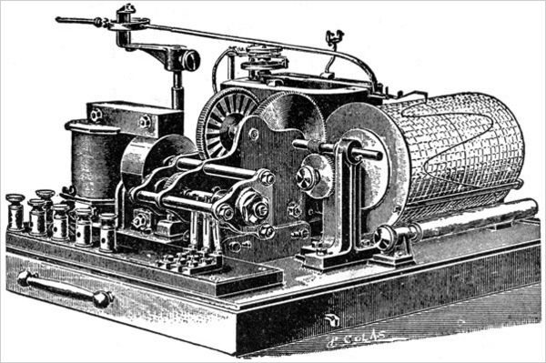
Hospitalier waveform recorder
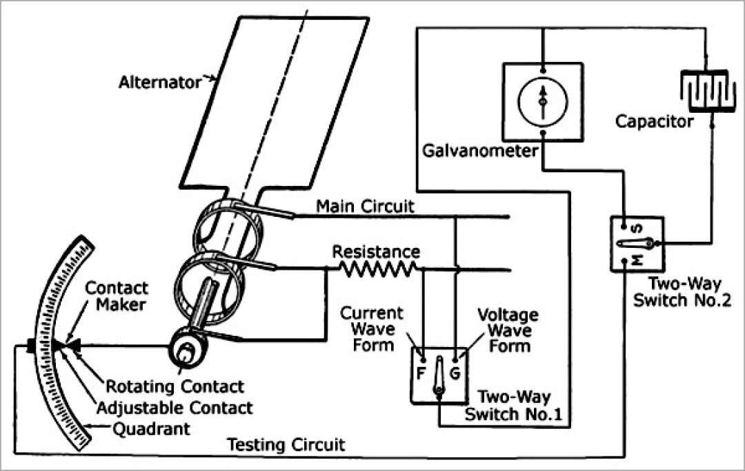
The principle of Hospitalier’s waveform recorder was similar to Joubert’s mechanical device. It plotted the current waveform through a repetitive measurement process. First, it stored the current using a capacitor, then discharged the capacitor to the galvanometer, controlling the pencil’s position based on the deflection angle of the galvanometer, ultimately plotting the current waveform point by point.
Since Hospitalier’s plotter used mechanical transmission, it couldn’t measure rapidly changing current signals in real-time and could only measure low-frequency signals.
Lens Reflection Beam Displaying Waveforms
(Photographic and Mirror Waveforms)
To overcome the frequency limitations of mechanical waveform plotters, in the early 1900s, British engineer William Duddell used a lens suspended in oil to reflect light and display current waveforms.
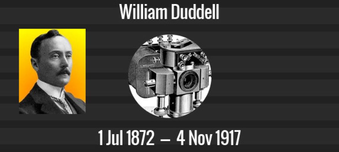
This lens was arranged with coils and placed in a magnetic field alongside the reflective lens. When the coil carried current, the lens would tilt according to the direction and magnitude of the current, amplifying the deflection angle through the reflected light beam, significantly increasing the sensitivity of current detection.
Cathode Ray Tube Oscilloscope
The invention of the cathode ray tube and its subsequent commercial application led to the birth of the first oscilloscope. In fact, as early as the late 19th century, German physicist Karl Ferdinand Braun had already invented a cathode ray tube oscilloscope for laboratory use and studied the behavior of electrons.
Using an electric field generated by charged electrodes could drive the deflection of a moving electron beam, forming a visible waveform trace on a surface coated with phosphorescent material.
In 1932, British Electronics Company A.C. Cossor developed commercial oscilloscope equipment based on this principle, which later became part of Raytheon.
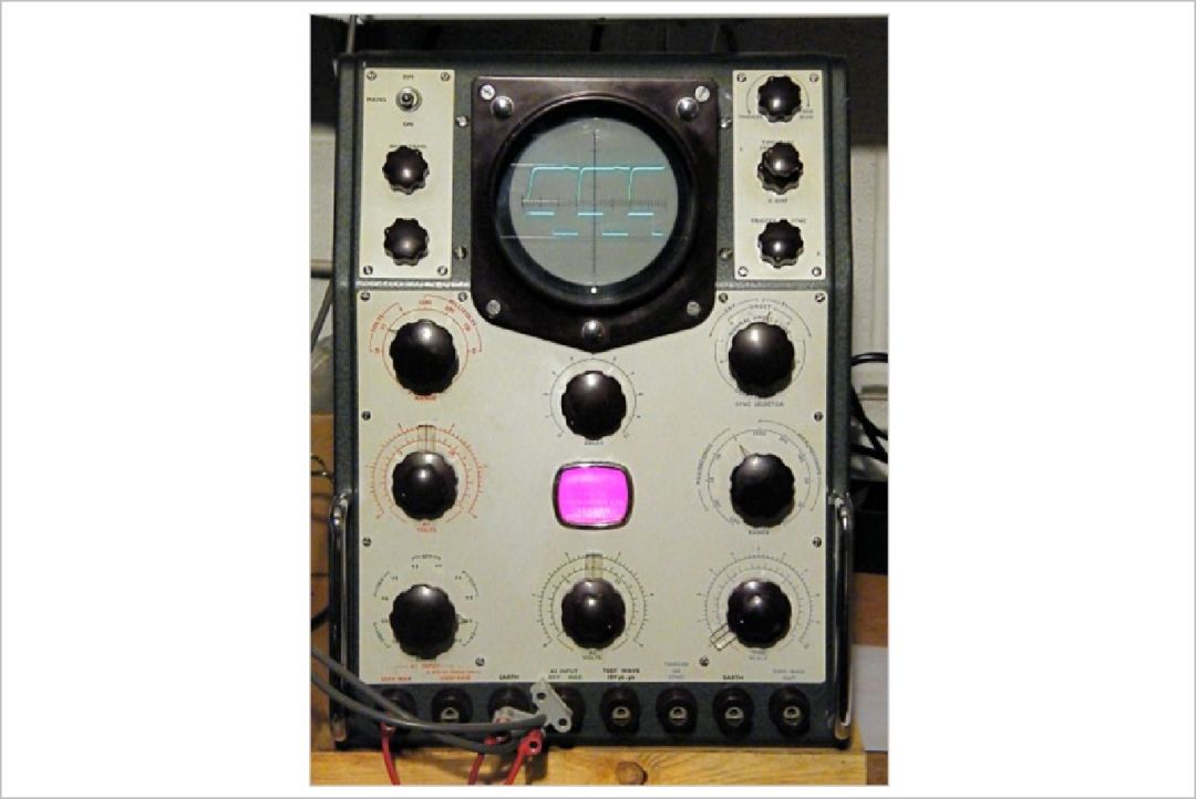
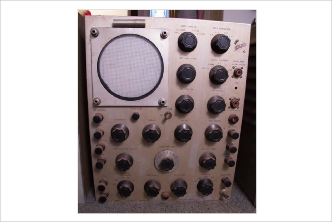
A.C.Cossor 1035 MKIII CRT Oscilloscope, 1950
During World War II, CRT oscilloscopes were widely used, and various types of phosphorescent materials were developed, each with different light intensity and afterglow duration. Some phosphorescent materials with slower decay were suitable for displaying low-frequency signals.
These early CRT oscilloscopes were not invented for precise measurement but to display the characteristics of electronic systems, making them not particularly convenient to use.
Frequency Trigger and Time Trigger
In the 1930s, DuMont Company made significant improvements to oscilloscopes, launching the DuMont 164 oscilloscope in 1939, equipped with a frequency-triggered scanning oscilloscope.
After World War II in 1946, Tektronix was founded. One of the company’s founders, Howard Vollum, invented the first time-triggered scanning oscilloscope, the 511 model. This 65-pound (29.5 kg) device consumed 180 watts and was priced at $795 at the time, equivalent to $10,000 in 2019. It could perform numerical measurements of signals with a bandwidth of 10Hz to 10MHz.
Tektronix 511 Oscilloscope
Tektronix remains a major provider of oscilloscope products in the market, having started with only 12 employees in 1947.
From Transistor Oscilloscopes to Digital Oscilloscopes
The early oscilloscopes were bulky and power-hungry because their core circuits were based on vacuum tube technology.
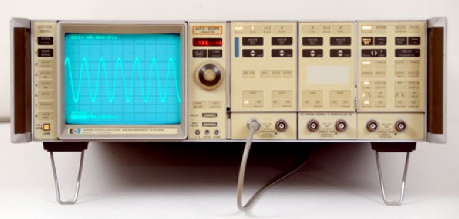
HP 1980A
Later, HP and LeCroy companies provided improved products. In 1969, HP’s HP1980A oscilloscope was launched, which was a fully transistorized oscilloscope with a bandwidth of 500kHz.
Subsequently, Tektronix engineer Hiro Moriyasu invented the digital oscilloscope. LeCroy’s WD2000 model, released in 1971, was a fully digital oscilloscope capable of storing 20 samples with a sampling time of 1ns.
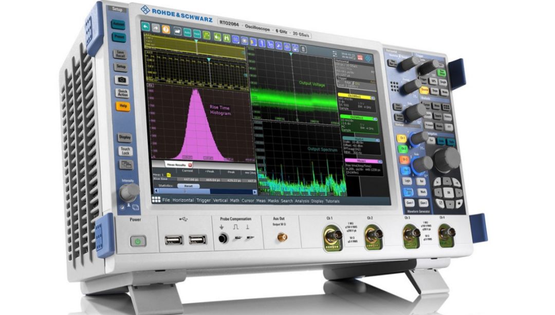
Modern Oscilloscopes
Today’s oscilloscopes develop at a pace that is almost hard to follow. From the 1930s to the 1980s, oscilloscopes saw significant improvements in measurement accuracy, speed, portability, and price.
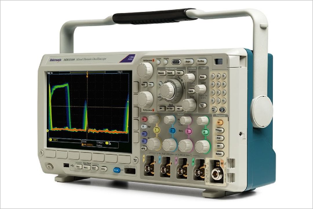
There have been tremendous advancements in aspects such as measurement bandwidth, channel count, size, and power consumption compared to earlier products. Additionally, the functionality has greatly expanded. For instance, the Tektronix MDO300 oscilloscope is a six-in-one measurement tool that includes an oscilloscope, digital multimeter, spectrum analyzer, logic analyzer, communication protocol analyzer, and signal function generator.
Moreover, there are other auxiliary devices for oscilloscopes, like the Pokit meter, which can provide oscilloscope functionality when paired with a smartphone.
The measurement and understanding of electronic signals have a long developmental history. The exploration of electrical signals was the original driving force behind this development, even though initial measurements of electricity were rudimentary. The invention of the oscilloscope also integrated advancements from many fields, such as a deeper understanding of the physics of electricity, the revelation of electromagnetic relationships, various inventions of automatic measurement techniques, and ultimately the invention of the cathode ray tube (CRT).
Reference: The Early History of the Oscilloscope: Amber and Frog Legs
https://www.allaboutcircuits.com/news/early-history-of-the-oscilloscope-amber-and-frog-legs/