The PY32MD310 is a high-performance 32-bit MCU based on the ARM Cortex-M0+ core, primarily aimed at the control of three-phase/single-phase brushless DC motors (BLDC) and permanent magnet synchronous motors (PMSM). The chip integrates up to 64 KB of Flash and 8 KB of SRAM memory, with a maximum operating frequency of 48 MHz. The chip operates within a temperature range of -40℃ to 105℃ and a voltage range of 1.7 V to 5.5 V.
The PY32MD310 microcontroller features a rich set of on-chip peripherals and a built-in three-phase half-bridge gate driver, designed to provide a highly integrated, reliable, and low-cost single-chip solution for various motor drive applications. The PY32MD310 is particularly suitable for applications such as fans, ceiling fans, floor fans, water pumps, power tools, model aircraft, and servo drives.
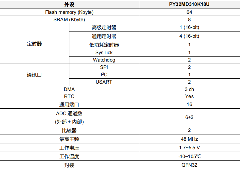
Main Features of the PY32MD310 Microcontroller:
1. Core and Memory
- CPU: 32-bit ARM Cortex-M0+, with a maximum clock frequency of 48 MHz.
- Memory: Up to 64 KB of Flash memory for program code storage; up to 8 KB of SRAM for runtime data storage.
2. Power Management and Low Power Consumption
- Operating Voltage: 2.0 V ~ 5.5 V.
- Low Power Modes: Supports Sleep and Stop modes, effectively reducing power consumption during idle periods.
- Reset System: Integrates Power-On/Power-Down Reset (POR/PDR), Brown-Out Reset (BOR), and Programmable Voltage Detection (PVD) to ensure stable operation in harsh power environments.
3. Motor Control Specific Peripherals (Core Advantages)
This is the key distinction of the PY32MD310 from general-purpose MCUs:
- Built-in Gate Driver:
- Operating Voltage: 6V ~ 36V, suitable for most low-voltage motor applications.
- Channels: Three-phase half-bridge drive, providing HO1/2/3 (high-side drive outputs) and LO1/2/3 (low-side drive outputs).
- Integrated LDO: Provides a 5V/50mA LDO output to power the MCU itself or external circuits.
- Built-in Dead Time: Hardware prevents shoot-through between high and low side transistors, enhancing safety.
- Integrated Operational Amplifier (Op-Amp): Two independent low-offset op-amps, typically used for sampling and amplifying motor phase currents, essential for implementing FOC algorithms.
- Advanced Timer: TIM1 is a 16-bit advanced control timer that supports complementary PWM output, dead-time insertion, and emergency brake (Break) functions, making it an ideal choice for generating PWM signals to drive three-phase motors.
- General-Purpose Timers: Multiple general-purpose timers (TIM3, TIM14, TIM16, TIM17) can be used for speed measurement, triggering ADC sampling, and other auxiliary functions.
4. Rich Basic Peripherals
- ADC: One 12-bit precision ADC, with up to 7 external channels + 2 internal channels (temperature sensor, internal reference voltage).
- Communication Interfaces:
- 2 x USART: Supports asynchronous serial communication with automatic baud rate detection.
- 2 x SPI: High-speed serial peripheral interface.
- 1 x I²C: Used for connecting sensors, EEPROMs, and other devices.
- Comparators (COMP): Two, can be used for overcurrent protection and other fast response functions.
- DMA: 3 channels, can reduce CPU load and achieve high-speed data transfer between peripherals and memory.
- Watchdog: Independent Watchdog (IWDG) and Window Watchdog (WWDG) to enhance system interference resistance.
- RTC: Real-time clock, supports calendar, alarm, and wake-up from Stop mode.