In-depth Analysis of Automotive Electronic Domain Control – Evolution of Central Control

Introduction:

In recent years, the domain control of automotive electronic control has transformed from a few forward-looking projects into a direction that all manufacturers strive to implement. Why can we now propose the concept of domain control and even central computing platforms? What functions can be controlled by domains? What possible paths are there for the future? This article will attempt to deeply analyze the evolution of electronic and electrical domain control based on my years of development experience in the automotive industry.

01

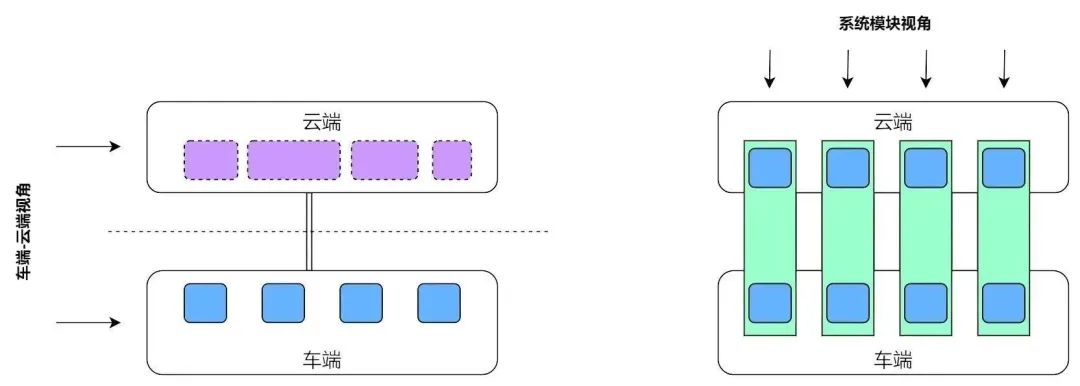
Why can we have domain control

Automotive electronic control, regardless of type, essentially expresses a simple control system model: “Sensor input => Processing => Actuator output.”
In the past embedded MCU environment of automotive electronics, input, processing, and output were integrated; the same ECU board collected signals, performed logic calculations, and finally drove the actuators, thus forming a closed loop.
In most cases, the ECU and the driven components were physically enclosed in the same housing, and the state of the components upon delivery included both electromechanical structures such as gear structures and software algorithm-carrying chips and PCBs, making hardware and software inseparable.
After being installed in the vehicle, the OEM was responsible for integrating the entire system interface and ensuring functionality coordination; the interface relationships had already been relatively fixed during the development process (for example, CAN signal matrices). In this state, each ECU primarily focused on managing its components, and whether they could flexibly collaborate at the vehicle level to produce functional innovations became secondary. Even if there was such an intention, the practical difficulty of change was significant. The electronic and electrical framework of the entire vehicle was essentially locked down by the mid-development stage, and any changes could require considerable effort.
The above describes the traditional state; the vehicle, as a complex industrial product, primarily requires precise coordination for long-term stable operation, and flexibility for changes was not a primary consideration, including for electronic control components.
The concept of domain control, or further the concept of a central computing platform, essentially aims to achieve one thing: separating and centralizing the logical processing and computation from the three aforementioned processes.
To achieve the separation and centralization of logic, several prerequisites must be met:
1. Upgrade of core processing chips, from MCU/MPU/SoC, significantly enhancing computational power;
2. Automotive Ethernet applications support high-speed real-time and large data volume transmission capabilities;
3. The large data transmission capacity further supports service-oriented middleware software architecture.
Processor Capability Rise
Taking the power domain as an example, the control system’s logical complexity in traditional automotive electronics is relatively high, currently utilizing 32-bit floating-point processors. Additionally, there are still many 8-bit and 16-bit microcontroller chips in other applications on the vehicle.
About seven or eight years ago, common MCU models for power systems, such as Infineon’s TC178x and NXP’s MPC574x, operated below 200MHz, with performance around 1.x~2.x DMIPS/MHz, estimating a computational power of ~400 DMIPS. Many controllers in the power and chassis domains could be implemented based on this computational level, such as EMS, VCU, BMS, EPS, ESP, etc., all utilizing the aforementioned MCU models.
Infineon gradually upgraded to TC2xx. With 1.7~2.4 DMIPS/MHz at 200MHz, three-core computation reached ~1200 DMIPS. Several times higher than before.
In recent years, there has been an upgrade to TC3xx, with TC39x reaching 4k DMIPS, multiplied several times.
Moreover, Infineon’s latest MPU TC4Dx has reached 8k DMIPS.
Additionally, the widely used MPU S32G has a processor section with 4xA53+3xM7, calculating at 2.3 DMIPS/MHz @ 1GHz and 2.14 DMIPS/MHz @ 400MHz, with a total processing power of over 11k DMIPS.
The widely used TDA4VM has a processor section including 2xA72 and 6xR5F, calculating at 7.3 DMIPS/MHz @ 2GHz and 2.45 DMIPS/MHz @ 1GHz, with a total processing power of over 40k DMIPS.
Further, taking Qualcomm’s SoC as an example, its subsequent SA85xx series aims for computational power in the range of 100~200k DMIPS.
The span from MCU to SoC has reached as much as 200 times.
Of course, the content handled by MPU and SoC is not just purely logical systems in embedded systems, but also includes running complex operating systems like Linux, and cooperating with other co-processing systems like DSP, GPU, NPU, etc., to complete complex image sensing and data-intensive algorithm processing, making a simple comparison of computational power with MCU somewhat unfair. However, overall, the point is to express that with the enhancement of processor capability, multiple control units from the past have the opportunity to run on the same chip; conversely, using the new generation MCU to handle traditional automotive electronic control system scenarios, even without considering the complexity of control strategies, may still waste many computational resources.
Application of Automotive Ethernet
Automotive Ethernet is another crucial factor enabling domain control separation. In automotive applications, the ability to exchange data in real-time is a basic requirement for almost all control functions. When mentioning real-time, the AVB/TSN protocol family first comes to mind. However, let’s first do a basic calculation.
Taking a 500kbps CAN network as an example, transmitting an 8-byte message frame takes approximately 216us (theoretical value, actual value will be slightly higher at 250~300us), with a theoretical transmission efficiency of 27us/Byte. Similarly, with a 100Mbps Ethernet bandwidth, a message frame of ~1500Bytes takes about 120us to transmit (theoretical value, actual value depends on network conditions and frame inter-delay, etc.), with a theoretical transmission efficiency of 0.08us/Byte. Comparatively, there is a difference of 200 times between the two.
This 200 times margin further provides ample space for the AVB/TSN protocol family to operate effectively.
Design of Service-Oriented Communication Middleware
The leap from CAN to Ethernet in terms of physical communication has enabled more flexible possibilities for information transmission. Service-oriented thinking is merely an engineering approach; strictly speaking, it is not a new concept in automobiles. The traditional diagnostic service protocol UDS is a form of service-oriented thinking, but even using multiple frames, the real-time data transmission volume is limited to several dozen bytes (excluding large multi-frame rewriting). However, the leap in communication efficiency brought by Ethernet has opened new possibilities for communication middleware.
Flexibility and efficiency are mutually balancing attributes; adopting a service-oriented architecture provides flexibility and plug-and-play capability, but also incurs additional protocol overhead, such as extra transmission of service discovery, handshake, and QoS information, which essentially reduces the information entropy coding efficiency.
After service-oriented transformation, similar signals may be packaged and sent multiple times in different service messages, or the same message may be consumed multiple times by different consumers, which is redundant compared to transmission based on CAN signals. Fortunately, the enhancement in physical communication efficiency provides ample space for information redundancy. When further upgraded to gigabit Ethernet, the bandwidth required for effective payload information in traditional automotive communication networks can almost be neglected, while redundancy and protocol overhead occupy the majority.
Because information serviceization provides flexible service configurations, as well as capabilities like hot-plugging of nodes and dynamic function configurations, it makes the collaboration and combination of functionalities between different control nodes within the vehicle possible, thus enabling the development of various vehicle functions that are easily adjustable and upgradeable over time.

02

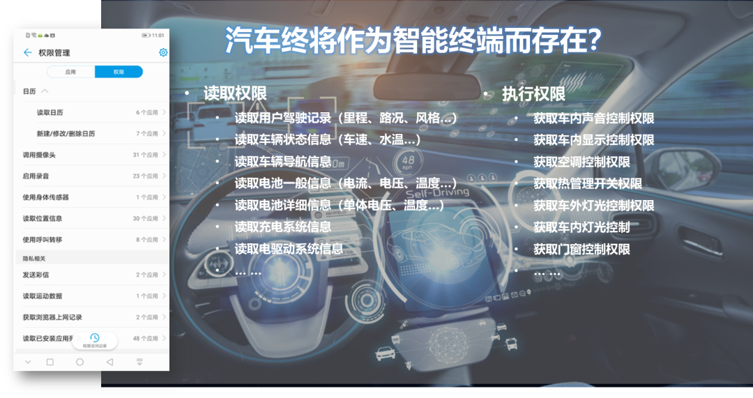
What functions can be domain-controlled

Five-Domain Model of Vehicle Control Functions
In-depth Analysis of Automotive Electronic Domain Control - Evolution of Central Control
Dividing vehicle functions into domains, it is possible to concentrate the functions within each domain. For example, the chassis domain, power domain, body domain, and the cabin domain and intelligent driving domain that have gradually formed with the intelligence of automobiles in recent years. The above five-domain model is currently a relatively common domain control architecture concept.
Next, in the process of moving towards domain control and further towards central computing platforms, can all functions be migrated to high-performance chips? The answer seems not entirely straightforward. In other words, which functions can be moved in, and which cannot, needs to be considered.
Time Scale of Vehicle Control
In-depth Analysis of Automotive Electronic Domain Control - Evolution of Central Control
Using a diagram to organize thoughts, along the horizontal axis is the time scale, and various automotive electronic controllers are listed above.
First, from a broad perspective, I believe we should establish the concept of a full time scale. The vehicle, as a system, possesses various functional elements with different time scales, spanning a wide range. Examples for each time scale are as follows:
100us level: belongs to ultra-fast computing scenarios. For example, the fuel injection timing in the engine management system must strictly determine the position of the crankshaft teeth; at 6000rpm, the time between teeth is only about 100us. Similarly, for motor vector control, at high speeds reaching 15000rpm, the calculation window for each position decoding and vector control is only 50~100us. This situation is limited by physical factors, making effective control impossible.
1ms level: quick computing scenarios. This is also considered a relatively fast computing step in embedded systems. Typical scenarios include electromagnetic valve control in chassis electronics, electromagnetic valve control in transmission systems, and throttle control in engine management systems, which must respond quickly to achieve good control effects due to the physical characteristics of the controlled objects.
10ms level: many control systems operate at this time scale, such as VCU, BMS, BCM, etc. Additionally, the logical control parts in EMS, MCU, ESP, etc., also work at this time step.
100ms level: real-time control systems with lower real-time requirements can operate at this time step, such as seat, sunroof, lighting, etc., in BCM, as well as air conditioning and thermal management systems. Furthermore, perception planning in ADAS currently operates at this time scale, though this is somewhat unavoidable, as even on high-performance SoCs, completing a full perception fusion algorithm takes this long.
1s/10s level: for traditional automotive electronic systems, this time is relatively slow. There are still some functions that can operate at this step, such as calculating health status or some hysteresis characteristics in BMS, or calculating energy balance states in hybrid systems, which are slower-changing behaviors that do not require rapid frequency updates.
Minutes/Hours level: there are few scenarios in traditional automotive electronic systems that operate at this time scale; at this time scale, information begins to rely on remote communication links between vehicles and the cloud to obtain information.
Function Centralization Based on Time Scale
Revisiting the above diagram, there are several points to consider:
1. Functions that fall between the two red lines on the time scale, specifically those with control steps between 5ms~100s, can be centralized for domain control. This software can be extracted from the original controllers and relocated to a centralized domain controller or vehicle central computing platform.
2. Functions closely related to the driven objects that require quick computations remain bound to the physical hardware of the controlled objects; additionally, some sensor signals sensitive to noise during long-distance transmission cannot be distanced from the physical hardware.
3. When the computational time scale increases and requires caching long-duration data to compute effective information, and when real-time requirements are low, consideration can be given to executing this in the cloud.
Focusing on point 1:
Functions related to the body domain and cabin entertainment domain, due to their relatively low sensitivity to real-time and safety, seem to be more acceptable for domain control.
However, it should be noted that most functions in the power and chassis domains, which are generally considered to require strong real-time and safety guarantees, can also be treated this way. The primary concern for domain control of power and chassis functions is the risk of insufficient real-time performance and the inability to timely complete control loops, especially when functions are safety-related, making them appear unreliable.
Analysis of Real-Time Control Disassembly
In-depth Analysis of Automotive Electronic Domain Control - Evolution of Central Control
We can consider this issue in the following way: assuming a control loop in the power or chassis domain operates at a step of 5ms and does not rely on external communication such as CAN (i.e., it will not introduce additional delays due to communication links).In 5ms, it needs to complete A – obtaining sensor information; B – logical processing; C – driving the controlled object, as shown in the left diagram.
Then, when the control function is migrated, its core logical processing function is transferred to the domain control or central controller. Accordingly, communication overhead B1 and B2 are added. It becomes A – obtaining sensor information; B0 – edge processing; B1 – sending information; B – logical processing; B2 – receiving information; C – driving the controlled object, as shown in the right diagram.
Not only have two communication steps B1 and B2 been added, introducing the risk of delay due to potential network congestion, but also, since the domain controller may run a complex operating system like Linux, task scheduling in step B may also introduce delays. Realistically, these possibilities exist, but let’s continue to verify and quantify the analysis.
1. Ethernet communication process B1/B2: For a simple structure with a hop count not exceeding 3 in automotive Ethernet, under TSN support, it can achieve delays in the hundreds of microseconds. Adding the inherent sending time of 120us, a round trip can be estimated to total about 1ms.
2. Logic computation task B:
(1) Task scheduling: For Real-Time Linux with the PREEMPT_RT real-time patch, the usual delay is in the hundreds of microseconds, with the worst-case scenario controlled within 1ms.
(2) Calculation time: Originally, the 5ms of the MCU cannot be fully utilized, estimating 4ms; with high-performance processors, it can be estimated to be halved to 2ms.
3. The area/edge processor responsible for sending and receiving agents B0 no longer undertakes logical computation tasks and can be set to run for 1ms.
In total, the above processes consume 4ms, and there is still some margin, with the actual situation likely being shorter.
It must be noted that in real scenarios, there will be practical issues such as interrupt response, scheduling, blocking, resource locking, priority, etc., that need to be properly addressed; the above is a discussion based on a simplified first-principles model.
Moreover, the electronic control logic itself possesses considerable potential for further tolerance to time limits.
To take a step back, the tasks themselves may also have a tolerance for occasional time delays; a 5ms baseline may allow for fluctuations of several milliseconds, which is a factor that should be considered in the original design. Moreover, fault diagnosis typically requires multiple cycles for confirmation.
To take another step back, most controllers may accept step lengths of 10ms or even 100ms, and with such time margins, it becomes even easier.
To take yet another step back, if multiple controllers form a control loop, originally, in addition to the inherent computation step length, there would also be additional communication delays from CAN transmission, which provides additional time margins.
Therefore, for most control functions in vehicles, migrating to a centralized domain control/central computing environment is entirely feasible.
Vehicle-Cloud Integration Perspective
From the above time scale analysis, another point that needs to be particularly emphasized is that for individual control systems, their time scales can also span a wide range. This is a new demand for smart connectivity in automobiles, emerging in the context of mature and cost-effective wireless communication and cloud data storage processing technologies.
In traditional automobiles, there is basically no concept of connectivity; each controller handles its own system. One could say that once the iron box is closed, it is unaware of the present day and the world. As long as it is powered on, it operates in its closed system, sensing – logic – executing, and so forth for decades.
In traditional embedded systems, computational and storage resources are very limited, making it almost impossible to handle long time scales (which may require caching a lot of intermediate data processing); furthermore, one cannot observe the average state of other similar models, so even if certain characteristics of the vehicle are clearly anomalous, there is no means to identify them. However, this need does exist; it just has not been realized due to the constraints of traditional embedded systems and has been accepted as normal.
With advancements in wireless communication technology and cloud data storage processing technology, the intelligent connectivity of vehicles has arrived. In this context, taking a different perspective, many control systems in vehicles can be extended to the cloud; only by combining the vehicle and cloud can a truly complete control system be formed, capable of covering the control needs across different time scales within this system.
In-depth Analysis of Automotive Electronic Domain Control - Evolution of Central Control
It should be noted that this perspective is not the same as the concept of some car manufacturers establishing a cloud platform for data storage, statistics, and visualization (as shown in the left diagram). Here, the emphasis is more on treating the local control units and the cloud control logic as a single system from the perspective of individual control systems, where the former is responsible for real-time control and data processing, while the latter handles tasks involving slow time scales but large data volume processing (as shown in the right diagram).
In-depth Analysis of Automotive Electronic Domain Control - Evolution of Central Control
Systems with particularly strong demands for vehicle-cloud integration include battery management systems (BMS) for battery status identification, cabin systems for driver habit recognition, and power systems for driving style and hybrid energy balance.

03

Possible Future Paths

Application Process
In a centralized state, running based on complex operating systems, whether macro-kernel (such as Linux) or micro-kernel (such as QNX), the original logical control programs in the embedded environment can evolve into one or more processes, relying on the real-time scheduling of the operating system to run. As mentioned, this design is feasible for most control scenarios.
Gradual Transition to Centralization
From the actual industry trend, it may gradually transition from cabin entertainment and body-related functions to chassis and power-related functions. This is determined by their nature; for high-risk applications with high performance requirements, engineers will instinctively start with the easier parts based on risk aversion.
However, the autonomous driving domain may be somewhat special. As a system closely related to power and chassis line control and safety, ideally, its overall computational logic flow should update as frequently as VCU, about every 10ms (following the system’s fastest IMU frequency). However, this speed is not just a matter of feasibility; it is a matter of capability, as current computational power does not meet this requirement (this is also the goal that Huizhi aims to solve). The perception, fusion, localization, and planning algorithm modules may be in a state of “data-intensive” + “computation-intensive,” with the computational intensity requirements soaring compared to traditional logic control algorithms. Achieving 10ms is not feasible. The actual computational flow is triggered by the camera frame rate, with 30FPS meaning 33ms to compute one frame, and to complete a full loop from perception to control, the entire link requires over 100ms. Therefore, the main part of autonomous driving, apart from regulatory control, has never run on an MCU since its inception, although from a real-time requirement perspective, it is more comparable to an application running on an MCU.
Additionally, there are many historical burdens; for example, chassis components like ESP rely not only on engineers’ expertise and development capabilities but also on professional testing environments, extensive product validation, and even lessons learned from accidents to gradually refine their software maturity. Unless a complete migration is possible, it seems challenging to achieve mass-production-level quality convincingly.
Therefore, overall, the transition will be gradual, incorporating more vehicle control functions from local to overall, moving from localized domain control to an overall vehicle central computing unit. More broadly, from the perspective of vehicle-cloud integration, the “vehicle central computing unit” can also be positioned as an “edge computing server,” while the cloud’s powerful computational and data storage capabilities become the “computational center.”
The state of vehicle + cloud integration covers features across various time scales from real-time to long periods, forming a complete control system.
Virtualization
The breakthrough may lie in the continuous enhancement of virtualization capabilities. Currently, virtualization can be categorized into several levels: pure software virtualization >> hardware-supported CPU virtualization >> GPU/NPU/… virtualization >> hardware-supported multi-container virtualization.
A control function’s operation requires multiple resources, including CPU, RAM, IO, Ethernet/CAN communications, SD/eMMC/UFS storage, and possibly more complex resources like NPU, GPU, Display, PCIe, MIPI-CSI, ISP, etc.
The process of increasing virtualization levels is essentially the process of achieving different levels of resource sharing and isolation based on various scene requirements. One can consider starting from Baremetal, moving to Hypervisor, then to the operating system kernel, cgroup, process, thread, coroutine, combined with hardware virtualization support, with each level offering different capabilities for resource allocation and isolation, along with corresponding performance overhead, making them suitable for different scenarios.
Possible future directions include:
First, high-performance computing-capable chips.
Second, the development of mature software infrastructure at different levels for vehicles.
Then, based on the nature of the overall vehicle control functions (such as real-time and isolation requirements), they can be deployed at the corresponding levels.
At that point, automobiles may truly transform into both a large industrial product and a form of consumer electronics. Functions that can be realized on mobile phones and tablets, along with features extended from the automobile’s inherent characteristics, will all be concentrated in this product.
In-depth Analysis of Automotive Electronic Domain Control - Evolution of Central Control
This article has many details that have not been discussed, and more so discusses the ideal end state. In today’s context of rapidly advancing domain control technology, the individual resolution of various specific engineering challenges by countless engineers is the most solid driving force for industry progress.
References:
[1] George K. Adam, “Real-Time Performance and Response Latency Measurements of Linux Kernels on Single-Board Computers”
[2] Michael M. Madden, “Challenges Using Linux as a Real-Time Operating System”
[3] Federico Reghenzani, Giuseppe Massari, and William Fornaciari, “The Real-Time Linux Kernel: A Survey on PREEMPT_RT”
[4] Pekka Varis, Thomas Leyrer, “Time-sensitive networking for industrial automation”
[5] https://www.curtisswrightds.com/sites/default/files/2021-10/Latency-Understanding-Delays-in-Embedded-Networks-white-paper.pdf
* Some images sourced from the internet

END

Click the business card below

Follow us now

Leave a Comment

×