
Brothers and sisters, long time no see!
I thought for a long time about the title of this issue, and I hope to make it a series of tweets.
Reflecting on the past few years, I am really touched by everyone’s companionship and support!
The reason I titled this issue as “My DIY Story” is to share more bits and pieces of this journey with everyone, and I hope everyone is willing to share their own experiences and thoughts.
You can send your DIY story articles to Brother P’s email:[email protected]
After receiving everyone’s articles, I will share them with the signature format you requested through the platform, so that everyone can understand and like you more.
This is a good way for everyone to get to know each other!
Let’s Start DIY
Today’s protagonist is a central control host used in my electronic studio. Before starting the DIY of this control host, you must first think about what functions and effects you ultimately want to achieve, and then design the technical framework. Similar DIY projects can be as complex or simple as necessary, as long as they suit you; there is no need to achieve “perfection”.
The design functional requirements for my control host are as follows for your reference: :
:
① Power control for multiple functional zones in the studio;
② Lighting control for the welding and testing areas;
③ Real-time display of power status in each zone;
④ Real-time display of temperature and humidity in the studio;
⑤ Statistics of electricity consumption information for each zone, including voltage, current, power consumption, effective power, etc.;
⑥ Control and status display of the UPS power host in the network area;
⑦ Control and status display of the desktop computer in the studio;
⑧ Control of the switch for the cabinet storing important items in the studio;
⑨ Ability to implement password-protected login functionality to ensure system security;
⑩ System settings can be flexibly configured and modified via a touch screen;
⑾ Reminder and confirmation mechanism in case of misoperation to avoid errors as much as possible;
⑿ Consider reserving data and functional interfaces such as wifi, serial port, ZigBee, etc., to provide certain system expansion capabilities.
Considering the above functional needs, I have previously completed the UI interface and MCU programming for the central control.
【Magic Door: Smart Control Center Touch Screen UI Interface Debut】.
Today we will complete the hardware assembly of this control host.
Here Comes the Picture Guy
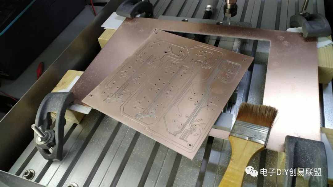
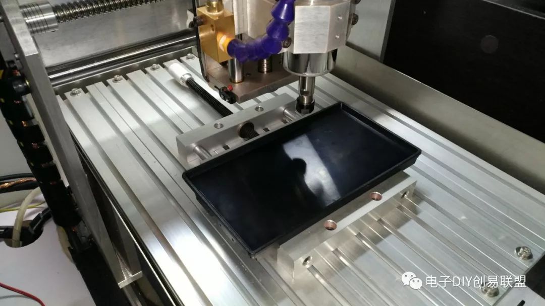
1. The first time using a carving machine to make a PCB board, below is the finished high-power interface board;
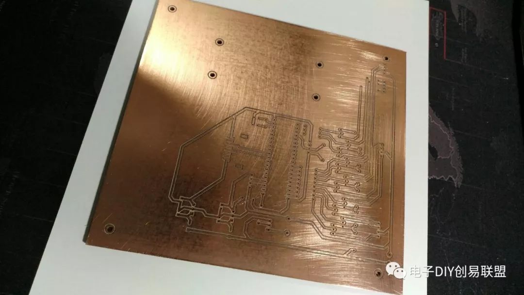
Below is the control board (low-power board) made by the carving machine;
2. After finishing the PCB board, we need to solder;
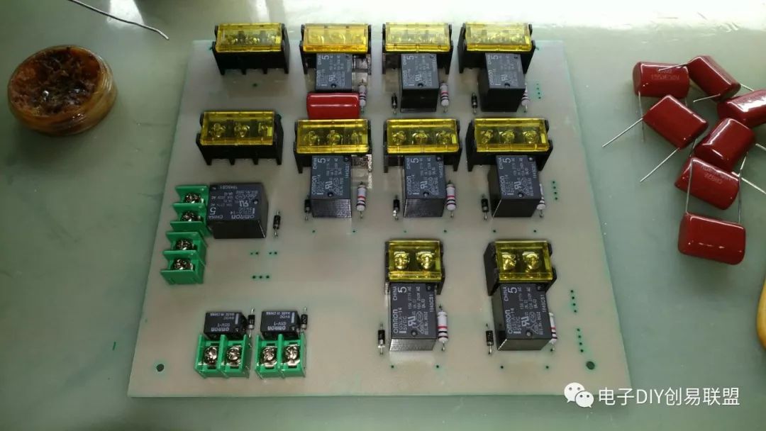
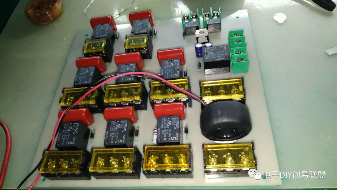
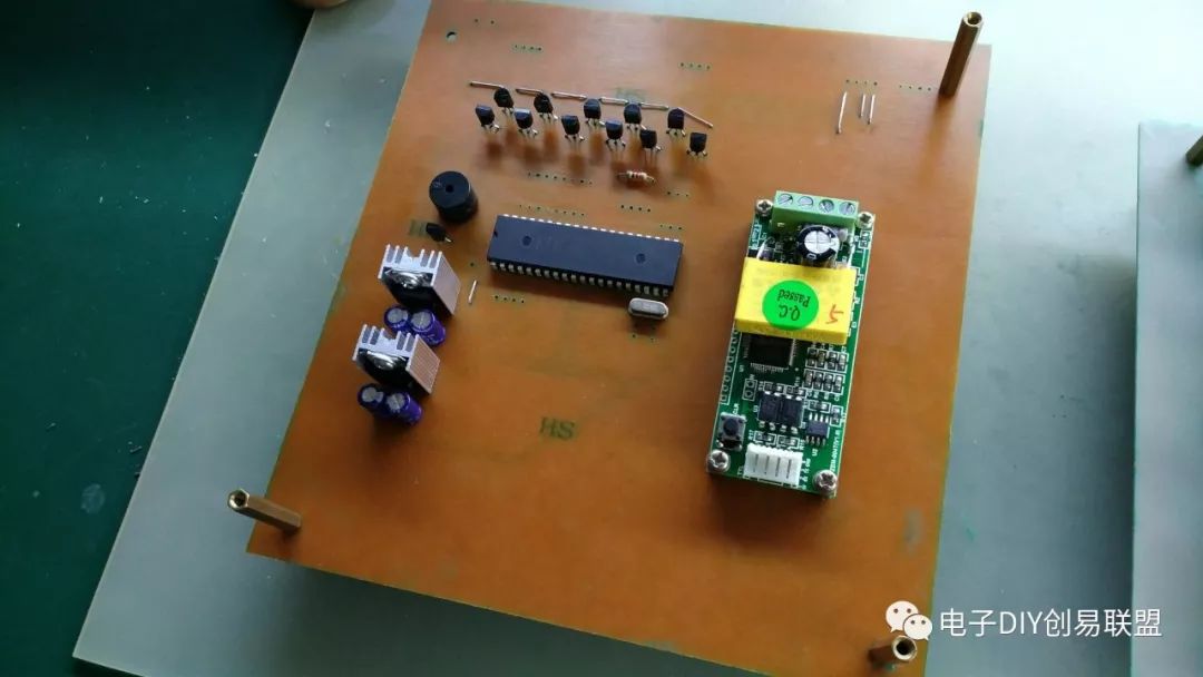
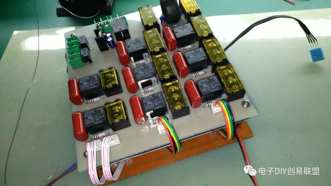
High-power interface board soldering completed:
Low-power board soldering completed:
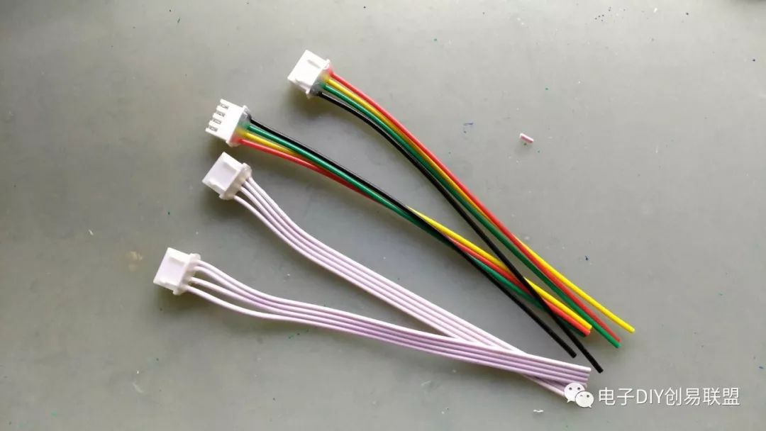
3. Making control wires;
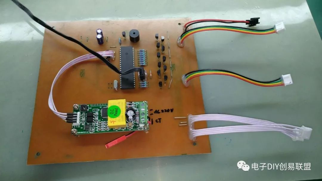
4. Soldering the control wires to the control board, interface soldering completed;
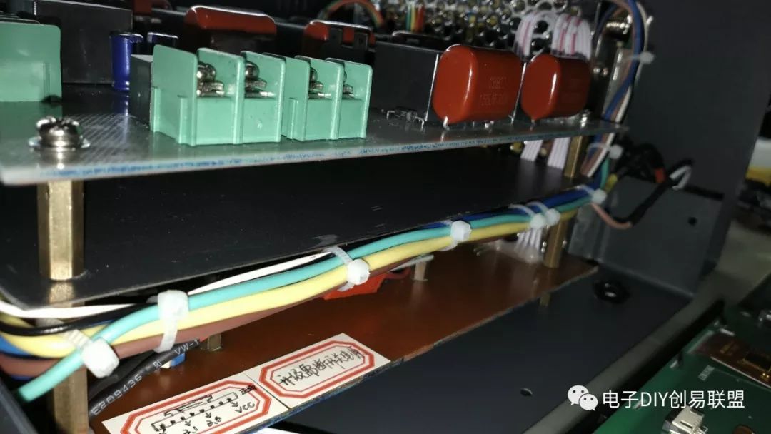
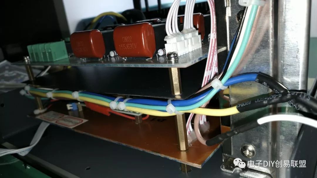
5. For safety reasons, a metal isolation plate was added between the high-power board and the low-power board;
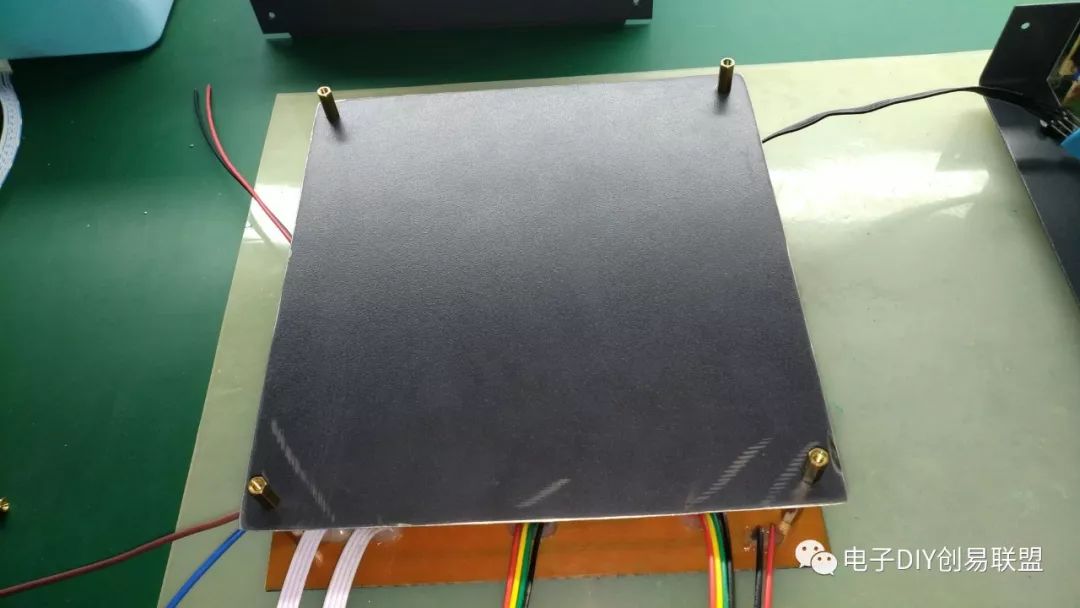
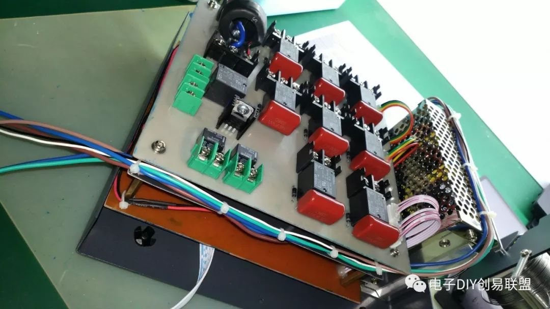
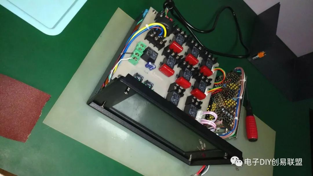
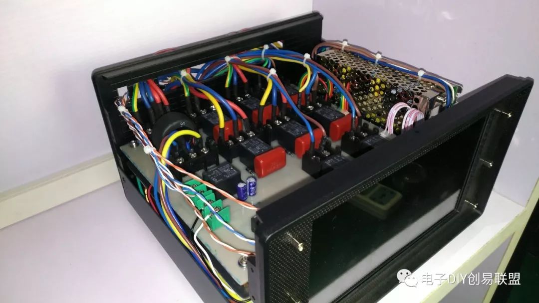
6. Install the high-power board with copper pillars layer by layer, and then connect the control wires;
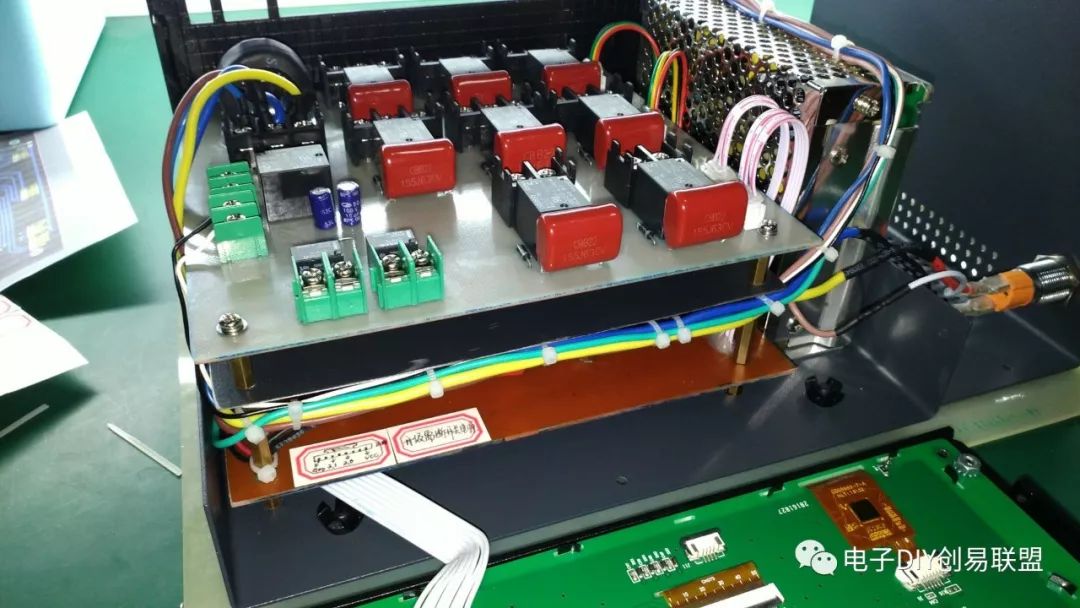
7. Prepare an empty chassis and start installing components into the chassis, first install the switch power supply;
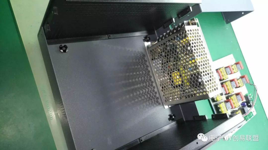
8. After reasonably determining the circuit board layout, fix the circuit board section;
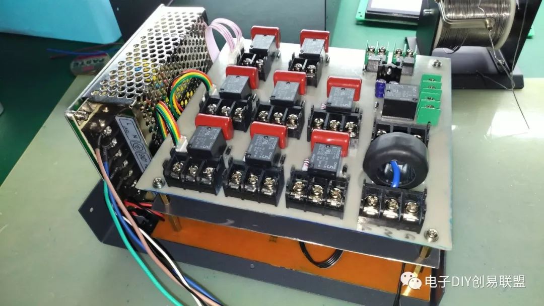
9. Start wiring, connect the switch power supply and circuit board, and make necessary fixes;
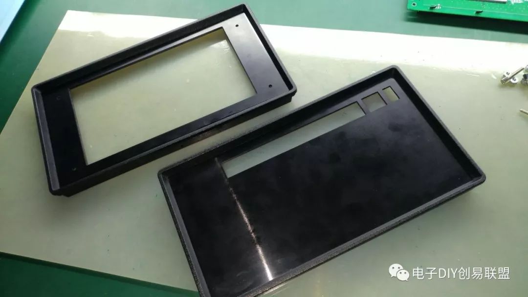
10. The carving machine makes a comeback, engraving the front and back panels of the chassis;
The engraved front and back panels:
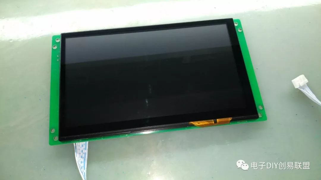
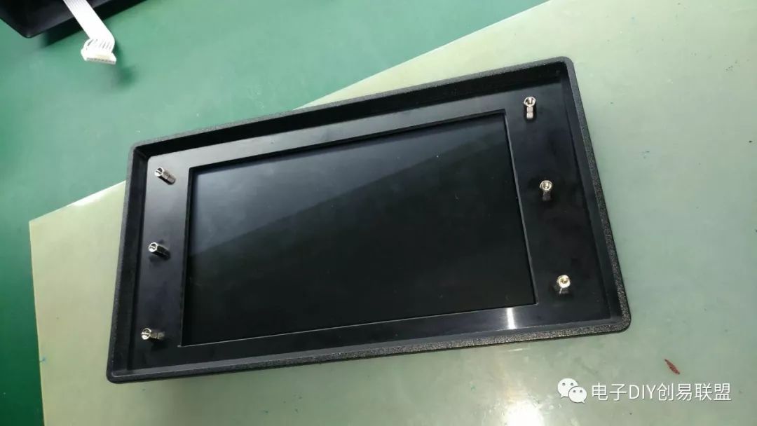
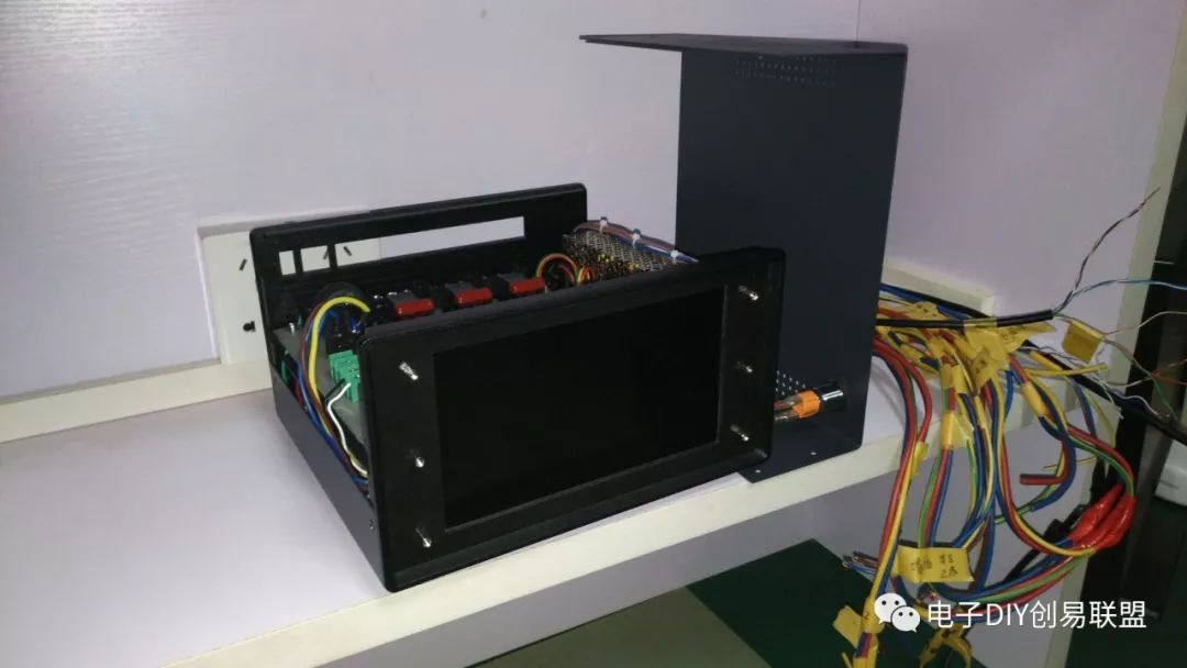
11. Prepare a 7-inch touch screen, ready for installation;
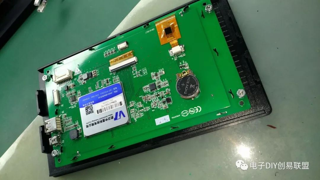
12. Fix the touch screen to the front panel;
13. The effect of the front panel installed on the chassis, check whether the space layout is designed correctly;
14. Here I need to explain briefly, I originally wanted to use the DIY method of the last carving machine to control the chassis to make the sticker for the front panel, but later found that the available panel area was too small, so I kept the installation screws, and it turned out that the effect was pretty good;
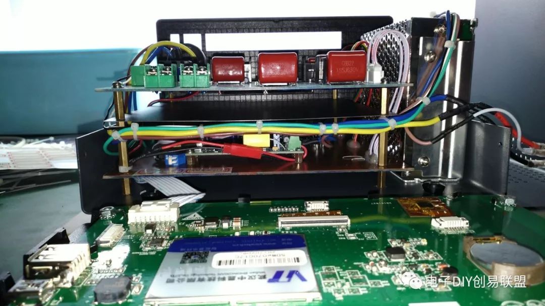
15. Check if all connections are correctly connected; only after confirming can power be applied for testing, which is very important!
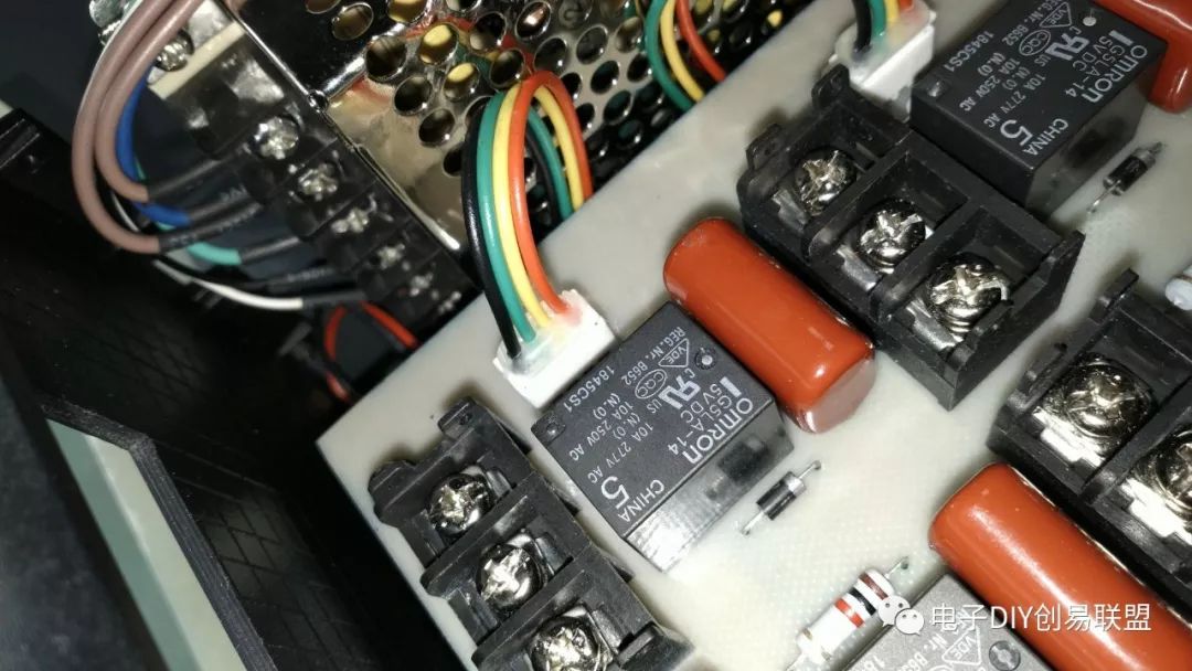
16. Check if the wiring is securely fixed;
17. After confirming everything is correct, reinstall the touch screen and connect the data cable of the touch screen;
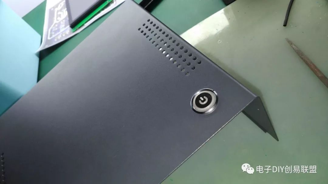
18. Use a hole punch to make holes and install the main power switch; we are one step closer to power testing;
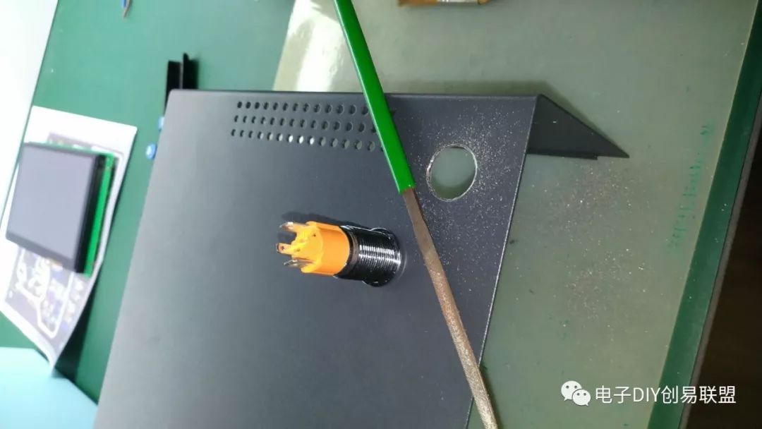
Main power switch installation completed:
19. After all components are installed and checked, we can start power testing to see if the system can run normally, and if the touch screen displays correctly. If everything is normal, the next step is to connect to the studio’s power circuit;
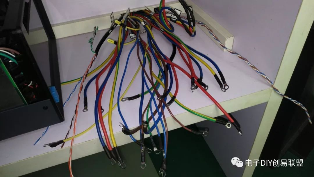
 20. The status of the original workbench power line, these power lines and control lines were designed during the initial construction of the studio. I unified all controlled area power lines and control lines to this position on the workbench;
21. Make sure all connection wires are properly connected;
22. After completing the terminal connections, we will finish the circuit connections for all leads to the control host;
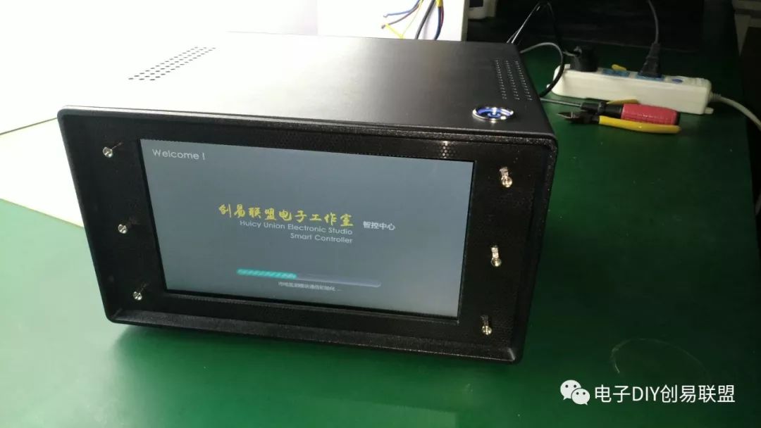
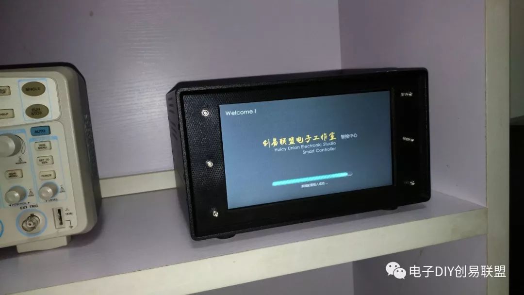
23. Install the outer shell, the DIY of the host is complete, here are two pictures of the completed effect:
(1) Startup interface:
(2) Control interface homepage
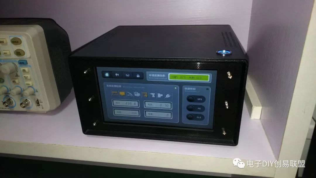
Above, we have completed the hardware DIY of this central control host. I can set a system login password, and using this control host allows for safe unified management and control of all controlled power and lighting in the studio, as well as real-time display of necessary status information and statistical data. If necessary, I can shoot a video for everyone to see; that will be a later discussion.
Final Words
If you want more people to know about your hobbies, please publish your DIY experiences or insights on www.huicy.cn or email [email protected], so that more people can like you!


Not following the Chuangyi Alliance
Would be embarrassing to say you’re an electronics DIY enthusiast!