Previous Part:
Step One: Applying RT Real-Time Patch to Raspberry Pi
Step Two: High-Speed SPI Communication Between Raspberry Pi and STM32
1. Robot Control Software Framework for Multi-Tasking
In microcontrollers, we can use timer interrupts, software scheduling, or directly use embedded operating systems like FreeRTOS or UCOSII to achieve timed execution of different control tasks. Since microcontrollers are single-core systems, even if multi-threading is constructed, it only actively releases resources when a certain thread is sleeping.
On the other hand, the Raspberry Pi has multiple CPUs that can achieve multi-core operation. When many high-speed motion control tasks are bound to a single CPU core, their speed and real-time performance far exceed the operating system scheduling of microcontrollers. As shown in the figure below, several main tasks in the MOCO-ML robot control system run at different frequencies, so we can adopt Linux multi-threading or multi-core multi-tasking methods to achieve this, thereby increasing the force control bandwidth to 1KHz, meeting the motion control frequency requirements of most robots:
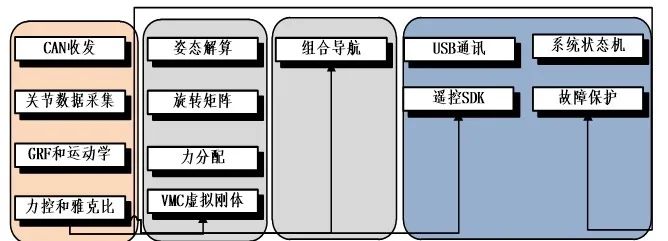
Operating System Threads Running Independently on STM32
As shown in the above figure, the modules further to the left have higher real-time requirements for computation, so we can combine many similar scheduling software modules into one large task to ensure they run on a separate CPU.
However, compared to multi-threading, inter-task data interaction poses a significant challenge. In a multi-threading framework, the most direct way is to define global variables for data function interaction, while in a multi-task framework, each task runs on different cores, and the real-time and data volume requirements for data interaction are very strict to ensure the robot’s operation.
Taking MIT’s quadruped robot software as an example, it uses LCM for inter-process data communication. LCM (Lightweight Communications and Marshalling) is a set of libraries containing various languages like Java, C, etc., specifically designed for real-time systems to send messages and handle data marshalling under high bandwidth and low latency conditions.
It provides a publish/subscribe messaging model and an automatic packaging/unpacking code generation tool supporting multiple programming languages. It was originally designed by MIT’s Urban Challenge team for the DARPA messaging system.
LCM is designed specifically for tightly-coupled systems connected via a local area network.
It is not suitable for the Internet. LCM is developed for soft real-time systems and allows packet loss by default to reduce latency.
https://link.zhihu.com/?target=http%3A//lcm-proj.github.io/
LCM has also been widely applied in autonomous driving, indicating that foreign software frameworks are more developed, with many necessary software modules already having mature libraries and corresponding packages to rely on. This is a core reflection of the technological strength of universities like MIT. Therefore, considering the soft and hardware control mechanisms of robots, we can modify the control framework in microcontrollers to a multi-process and multi-threaded structure.
First, we can divide the main functions of the robot into three levels: the first is the low-level servo drive: this part mainly involves SPI communication between the Raspberry Pi and the microcontroller. To ensure high-speed data transmission, a separate process needs to be allocated, along with appropriate protections;
The second level is the motion control layer: this part mainly completes the estimation of the robot’s motion state and feedback control; the third layer is the navigation planning layer: this part mainly completes the robot’s path planning and remote command processing. Additionally, many global protections can also be placed in this layer, so the software framework of the robot in the Raspberry Pi is as follows:
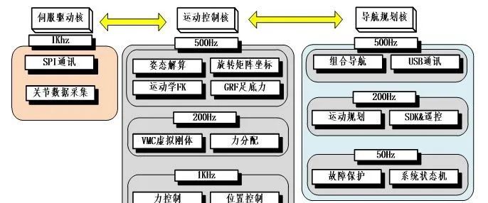
Multi-Core Architecture Under Raspberry Pi
2. Shared Memory and Data Interaction
Based on LCM, lightweight real-time data interaction can be achieved, but it requires installing the corresponding library to support it. In Linux systems, data interaction can also be achieved through shared memory, which is one of the simplest methods of inter-process communication.
Shared memory allows two or more processes to access the same block of memory, just as the malloc() function returns pointers to the same physical memory area for different processes. When one process changes the content at this address, other processes will notice this change.
Therefore, I referred to many examples of shared memory online to implement my own inter-process communication interface. First, we built a shared memory interface for the servo layer servo_task.
This layer mainly uses the SPI interface to read encoder data and IMU motion sensor data returned by the microcontroller. Furthermore, we allocate a simple memory space and store it in four bytes according to the floating-point protocol, starting with initializing the memory writing:
struct shareMemory { int flag=0; // Used as a flag, non-zero: indicates readable, 0 indicates writable unsigned char szMsg[MEM_SIZE]; }; struct shareMemory shareMemory_spi;The structure re-allocates MEM_SIZE character type variable memory. After that, we add the following code in the initialization, where MEM_SPI is the memory ID, and reading and writing need to be consistent:
// Shared Memory int shmid_rx = shmget((key_t)MEM_SPI, sizeof(shareMemory_spi), 0666|IPC_CREAT); // Returns -1 on failure, assume success. // 0666 indicates permissions, similar to files. For example, 0644 indicates that a process creating shared memory can read and write data to the shared memory owned by the creator, while other user-created processes can only read the shared memory. void *shm_rx = shmat(shmid_rx, (void*)0, 0); // Returns -1 on failure, assume success shareMemory *pshm_rx = (shareMemory*)shm_rx; pshm_rx->flag = 0; printf("Memory SPI attached at %p\n",shm_rx);In the main loop, after reading the SPI data, we write it into memory and change the data refresh flag:
// Shared Memory Write if(pshm_rx->flag == 0) { if(!mem_connect){ printf("MEM SPI CONNECT!!!\n"); mem_connect=1; } mem_loss_cnt=0; memory_write(); for(int k=0;k<MEM_SIZE/2-1;k++) pshm_rx->szMsg[k]=mem_write_buf[k]; for(int k=MEM_SIZE/2;k<MEM_SIZE;k++) mem_read_buf[k]=pshm_rx->szMsg[k]; memory_read(); pshm_rx->flag = 1; }else mem_loss_cnt+=sys_dt;During writing, we first read the sensor data as floating points and store them sequentially into the corresponding buffer array write_buf:
void memory_write(void)// Write to Memory{ static float temp=0; mem_write_cnt=0; setDataFloat_mem( spi_rx.att[0]); setDataFloat_mem( spi_rx.att[1]); setDataFloat_mem( spi_rx.att[2]); setDataFloat_mem( spi_rx.att_rate[0]); setDataFloat_mem( spi_rx.att_rate[1]); setDataFloat_mem( spi_rx.att_rate[2]); setDataFloat_mem( spi_rx.acc_b[0]); setDataFloat_mem( spi_rx.acc_b[1]); setDataFloat_mem( spi_rx.acc_b[2]); for (int i = 0; i < 4; i++) { setDataFloat_mem(spi_rx.q[i][0]); setDataFloat_mem(spi_rx.q[i][1]); setDataFloat_mem(spi_rx.tau[i][0]); setDataFloat_mem(spi_rx.tau[i][1]); }}Then we assign it to the array allocated in shared memory, so another process can read it after judging the flag change. Note that here, I referred to the idea of synchronous read/write of SPI, using the front half of the array for writing and the back half for reading data from another process. The reading function essentially reassembles the data in memory back into floating-point numbers.
void memory_read(void){// Read from Memoryint mem_read_cnt=MEM_SIZE/2;float test1,test2;for (int i = 0; i < 4; i++){ spi_tx.q_set[i][0] = floatFromData_spi(mem_read_buf, &mem_read_cnt); spi_tx.q_set[i][1] = floatFromData_spi(mem_read_buf, &mem_read_cnt); spi_tx.q_reset[i][0] = floatFromData_spi(mem_read_buf, &mem_read_cnt); spi_tx.q_reset[i][1] = floatFromData_spi(mem_read_buf, &mem_read_cnt); spi_tx.tau_ff[i][0] = floatFromData_spi(mem_read_buf, &mem_read_cnt); spi_tx.tau_ff[i][1] = floatFromData_spi(mem_read_buf, &mem_read_cnt);}spi_tx.max_i= floatFromData_spi(mem_read_buf, &mem_read_cnt);spi_tx.kp= floatFromData_spi(mem_read_buf, &mem_read_cnt);spi_tx.ki= floatFromData_spi(mem_read_buf, &mem_read_cnt);spi_tx.kd= floatFromData_spi(mem_read_buf, &mem_read_cnt);spi_tx.en_motor= mem_read_buf[mem_read_cnt++];spi_tx.reser_q= mem_read_buf[mem_read_cnt++];spi_tx.reset_err= mem_read_buf[mem_read_cnt++];}Therefore, after each SPI reading, we write the data into memory and parse the second half of the memory for data from other processes, finally setting the flag to 1;
For the receiving process, such as our control_task, we first need to build a structure identical to the sending one:
struct shareMemory { int flag=0; // Used as a flag, non-zero: indicates readable, 0 indicates writable unsigned char szMsg[MEM_SIZE]; }; struct shareMemory shareMemory_spi;The initialization part is slightly different, ensuring that the memory ID accessed by MEM_SPI is consistent:
int shmid_rx = shmget((key_t)MEM_SPI, sizeof(shareMemory_spi), 0666|IPC_CREAT); // Returns -1 on failure, assume success void *shm_rx = shmat(shmid_rx, 0, 0); shareMemory *pshm_rx = (shareMemory*)shm_rx; printf("Memory SPI attached at %p\n",shm_rx);Then in the main function, we check if the flag is 1, indicating data refresh, and start reading. Thus, the read/write order is opposite to sending: read first, write second, and then set the flag to 0, completing a synchronous read/write:
if(pshm_rx->flag == 1) { if(!mem_connect){ printf("MEM SPI CONNECT!!!\n"); mem_connect=1; } mem_loss_cnt=0; for(int k=0;k<MEM_SIZE/2-1;k++) mem_read_buf[k]=pshm_rx->szMsg[k]; memory_read(); memory_write(); for(int k=MEM_SIZE/2;k<MEM_SIZE;k++) pshm_rx->szMsg[k]=mem_write_buf[k]; pshm_rx->flag = 0; } Thus, when both tasks are running, data can be transmitted between them through shared memory. Of course, the way I implemented it is relatively crude, similar to a traditional response mode, but with limited capabilities, I can first ensure that both parts can function.
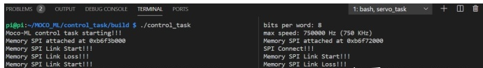
When starting the servo and control programs on two different terminals, we can observe successful data exchange, and the communication frequency can guarantee the batch rate with SPI reception. In the figure below, the servo node transmits the posture angles calculated by STM32 to the control node and prints them:
The above method is implemented based on my personal understanding of shared memory data transmission. However, it obviously has many issues, such as:
(1) It adopts a response mechanism, so data synchronization can only be achieved after SPI transmission is completed, thus the refresh of memory data is affected by SPI communication frequency;
(2) Memory synchronization cannot achieve floating-point transmission, requiring custom encoding and decoding;
(3) Memory synchronization only supports one-to-one transmission;

“Introduction to Baidu PaddlePaddle Deep Learning Platform Development“
In this course, students will gain a clear understanding of the Baidu PaddlePaddle deep learning platform, including the features of the paddle deep learning framework and the use of the Ai Studio platform.

(Scan the QR code to view course details)