
Previous Article: Understanding FreeRTOS Application Scenarios
In this article, the term “stack” refers to the memory area accessed by the computer (including MCU) processor through the stack pointer register. Common access methods include Push/Pop, as well as indirect addressing based on the stack pointer register. Let’s first review how local variables are stored in C language. For example, when the main() function calls func1(), and then func1() calls sub2(), as shown in the figure below.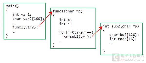
When the CPU executes the sub2() function, the local variables in main() and func1() are out of scope, but their storage is preserved. Therefore, by passing pointers as parameters, sub2() can access the data of the local variables in main(). However, when the sub2() function returns, the space occupied by the local variables of sub2() is reclaimed, and even if it returns a pointer value to func1(), the address obtained by func1() is invalid. This is because when a C language function is executed, it reserves a space on the stack for its local variables and saves important registers. Generally, the current stack pointer is saved at the entrance of the function and restored before returning.
The usage of the stack in the above calling relationship is generally as follows: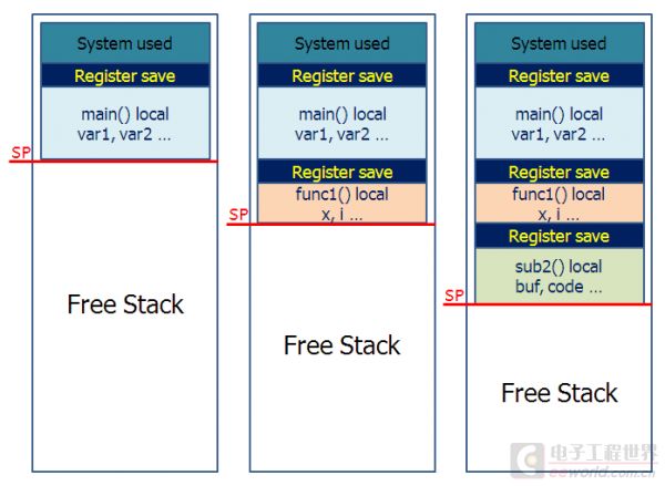
From left to right, it is the process of function calls (nesting); from right to left is the process of functions returning one by one. In addition, the interrupt service routine (ISR) is also a type of function, slightly special. When an interrupt occurs, the CPU retrieves the entry address of the corresponding interrupt service routine from the interrupt vector table, automatically saves critical registers onto the stack, and then jumps to the entry address of the interrupt service routine to execute it. The interrupt service routine also reserves a space on the stack for its local variables and saves some registers that are not automatically saved. The main program and its called subroutines have no way of knowing when the interrupt service routine is called (only when using sleep instructions to pause execution is an exception). How to implement multitasking? As mentioned above, suppose a multitasking requirement is that sub2() wants to wait for a while but does not return, allowing func1() to continue executing. This implies that func1() thinks sub2() has already returned, which is clearly incorrect because once sub2() returns, the stack pointer is reverted to the state when func1() was executing, and the stack space reserved by sub2() is reclaimed and can be overwritten at any time (for example, if func1() calls any subfunctions or if an interrupt occurs), making it impossible for it to continue executing. It can be analyzed that to achieve multitasking, each task function must have its own stack space that remains valid during the task period and cannot be overwritten by other tasks. Thus, we need a scheduler to coordinate stack usage. Furthermore, tasks are at the same level and do not have mutual calling relationships, so they can only be called by the scheduler. Let’s improve and see if the stack is used as follows:
Wait, how does the scheduler know in advance how much stack space a task function will use? C language function calls do not need to know how much stack a subfunction uses—you can use it all, it’s all yours. But for multitasking, one task cannot use all the stack.
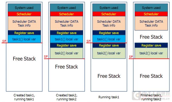
There are still issues: in the third diagram from the left, if task1() wants to call a subroutine, it cannot. Because if it modifies the stack pointer, it will destroy the private data of task2(). If subroutines cannot be called, inter-task communication and synchronization in a multitasking system will be difficult to achieve…
Therefore, the stack space reserved for a task cannot just be the size of the stack space occupied by the task’s function itself. Now let’s take a look at how FreeRTOS manages the stack of tasks.
Using the diagram from the Tutorial Guide
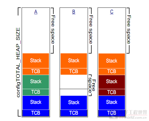
FreeRTOS allocates a block of memory to store the stack of tasks and the task configuration (Task Control Block). This space is managed by FreeRTOS itself, and the creation and destruction of tasks correspond to the allocation and release of this memory (note that it is independent of the C function malloc() and free() memory management).
This is why when creating a task, it is necessary to specify the stack size—allocate as much as needed, and if it is insufficient, the task cannot be created; if too much is allocated, it cannot be exceeded, regardless of how the task is nested calling functions. In addition, FreeRTOS also has dynamic memory allocation functionality, allowing tasks to use memory beyond the stack. However, the pre-specified stack size is important because resources on microcontrollers are limited, and excessive allocation will affect other tasks. Fortunately, tasks running on microcontrollers are generally not too complex, and stack usage can be determined through analysis or testing during development. My first FreeRTOS program created two tasks to drive two LEDs. In main() and within the task functions, I output the addresses of their respective local variables to determine the stack allocation position:
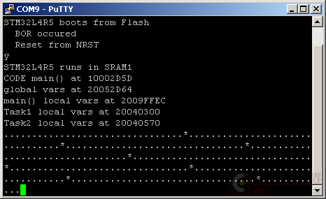
The output from the serial port shows that the local variables of main() are located on the total stack, which is near the position of the stack pointer after the total program initialization (usually at the end of SRAM). Global variables are arranged sequentially in the .data or .bss segments. The stack allocation for the two tasks is at the lower end of the memory, appearing to be taken from a fixed allocation of memory in the .bss segment.
By using the arm-none-eabi-objdump tool to view the statically allocated memory in the generated ELF file:
-
20040000 g .data 00000000 _sdata
-
20040000 l O .data 00000004 uxCriticalNesting
-
20040000 l d .data 00000000 .data
-
20040004 l O .data 00000004 xFreeBytesRemaining
-
20040008 g .bss 00000000 __bss_start__
-
20040008 g .bss 00000000 _sbss
-
20040008 g .data 00000000 _edata
-
20040008 l d .bss 00000000 .bss
-
2004001c l O .bss 00000014 xPendingReadyList
-
20040030 l O .bss 00000004 pxDelayedTaskList
-
20040034 l O .bss 00000004 xNextTaskUnblockTime
-
20040038 l O .bss 00000004 xTickCount
-
2004003c g O .bss 00000004 pxCurrentTCB
-
20040040 l O .bss 00000004 uxTopReadyPriority
-
20040044 l O .bss 00000004 pxOverflowDelayedTaskList
-
20040048 l O .bss 00000004 uxCurrentNumberOfTasks
-
2004004c l O .bss 00000064 pxReadyTasksLists
-
200400b0 l O .bss 00000014 xDelayedTaskList1
-
200400c4 l O .bss 00000014 xDelayedTaskList2
-
200400d8 l O .bss 00000014 xTasksWaitingTermination
-
200400ec l O .bss 00000004 xSchedulerRunning
-
200400f0 l O .bss 00000004 uxTaskNumber
-
200400f4 l O .bss 00000004 uxDeletedTasksWaitingCleanUp
-
200400f8 l O .bss 00000004 uxSchedulerSuspended
-
200400fc l O .bss 00000004 xIdleTaskHandle
-
20040100 l O .bss 00000004 xNumOfOverflows
-
20040104 l O .bss 00000004 uxPendedTicks
-
20040108 l O .bss 00000004 xYieldPending
-
2004010c l O .bss 00000001 ucMaxSysCallPriority
-
20040110 l O .bss 00000004 ulMaxPRIGROUPValue
-
20040114 l O .bss 00000008 xStart
-
2004011c l O .bss 00000004 xHeapHasBeenInitialised.5018
-
20040120 l O .bss 00012c00 ucHeap
-
20052d20 l O .bss 00000008 xEnd
-
20052d28 l O .bss 00000004 xTimerQueue
-
20052d2c l O .bss 00000014 xActiveTimerList1
-
20052d40 l O .bss 00000014 xActiveTimerList2
-
20052d54 l O .bss 00000004 pxCurrentTimerList
-
20052d58 l O .bss 00000004 pxOverflowTimerList
-
20052d5c l O .bss 00000004 xTimerTaskHandle
-
20052d60 l O .bss 00000004 xLastTime.5299
-
20052d64 g O .bss 00000010 dummy
-
20052d74 g O .bss 00000040 xQueueRegistry
-
20052db4 g .bss 00000000 __bss_end__
-
20052db4 g .bss 00000000 _ebss
20040008 l O .bss 00000014 xSuspendedTaskList
It can be seen that 0x12c00 bytes are fixedly allocated to ucHeap, and the stack of the two tasks is taken from this space. In the FreeRTOSConfig.h header file I used, there is a line:
#define configTOTAL_HEAP_SIZE ( ( size_t ) ( 75 * 1024 ) )
This value corresponds exactly to the memory size occupied by the ucHeap variable. Let’s study the details of FreeRTOS implementation.
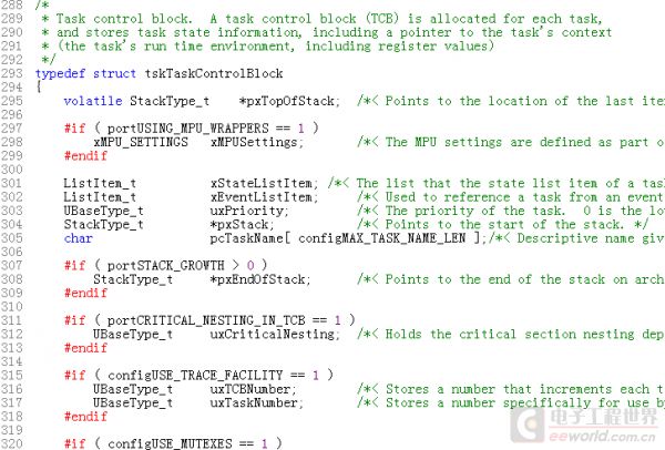
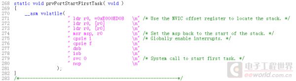
The port I used is in the CORTEX_M3 directory (although running on a Cortex-m4 CPU, it does not use the floating-point processor), in the FreeRTOS code tasks.c, a structure is defined to describe the TCB data.
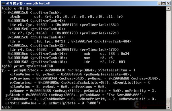
Among them, prvInitialiseNewTask() calls the platform-dependent pxPortInitialiseStack() in port.c to initialize the stack, let’s take a look:
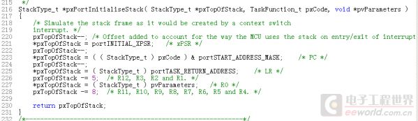
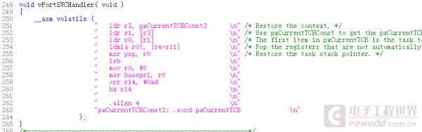
No, if you understand the exception handling mechanism of ARM cortex-m, you will realize that the content of the LR register in the Exception handler (including ISR) state does not store the return address. This is also why you can write ARM cortex-m interrupt service routines with ordinary C functions, while other platforms often require the use of the interrupt keyword to tell the compiler to use interrupt return instructions. In the code of vPortSVCHandler, before the bx r14 (LR is an alias for R14) instruction, there is an orr r14, #0xd instruction that modifies the low 4 bits of the LR register to 0xd, indicating a return to Thread mode execution and using the PSP stack register, thus switching to the task’s stack.
Recommended Reading
Understanding FreeRTOS DIY Temperature-Controlled Rice Box
Understanding FreeRTOS DIY PCB Circuit Board
Understanding FreeRTOS My Self-Used Organizational Structure for a Complex MCU Application
Understanding FreeRTOS A Brief Discussion on MCU Application Program Architecture
Understanding FreeRTOS A Gift for Beginners: Understanding the Clock Tree of STM32
Understanding FreeRTOS Learning Notes — Application Scenarios
Understanding FreeRTOS Enumeration Variables and Macros Applications
Understanding FreeRTOS Building a Beautiful VFD Voice Clock
Understanding FreeRTOS Step-by-Step Guide to Making a Mini Power Bank with LED Emergency Light
Understanding FreeRTOS Discussion on Voltage Regulation