 Article from “Power Equipment Management” magazine
The clamp ammeter is composed of a current transformer and an ammeter. The core of the current transformer can open when the clamp is tightened; the wire carrying the current to be measured can pass through the opening of the core without being cut. When the clamp is released, the core closes.
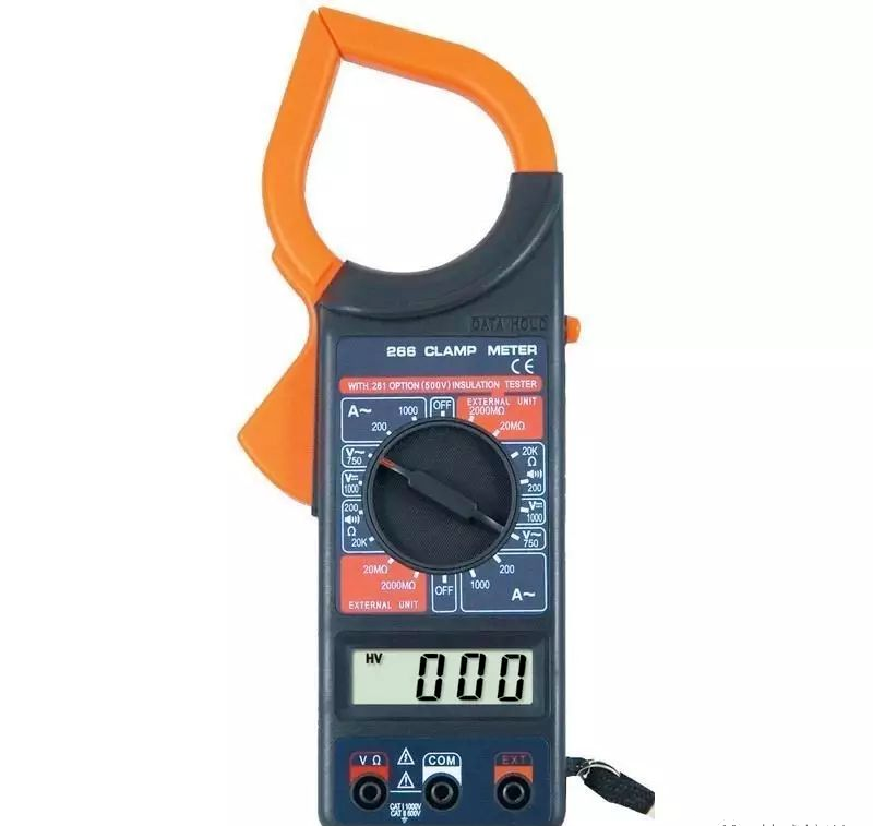
The clamp ammeter is composed of a current transformer and an ammeter. The core of the current transformer can open when the clamp is tightened; the wire carrying the current to be measured can pass through the opening of the core without being cut. When the clamp is released, the core closes.
Structure and Usage of Clamp Ammeter
When we need to measure current without breaking the circuit, we need to use a clamp ammeter (sometimes referred to as a clamp meter). A clamp ammeter is an instrument used to measure the current in an electrical circuit that is in operation, and it is a commonly used measuring tool for electricians. Clamp ammeters are divided into two categories: clamp AC ammeters and clamp AC/DC ammeters; some can also measure AC voltage.
Structure:
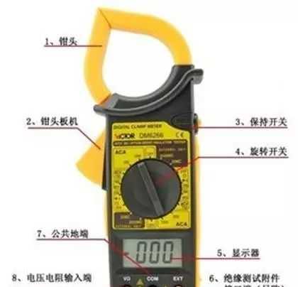
The clamp AC ammeter is essentially composed of a current transformer and a rectifying instrument. The wire being measured acts as the primary winding of the current transformer, while the secondary winding of the current transformer is on the core, connected to the rectifying instrument. Based on a certain proportional relationship between the primary and secondary windings of the current transformer, the rectifying instrument can display the current value of the measured circuit.
The clamp AC/DC meter is an electromagnetic instrument, with the wire being measured placed in the clamp acting as the excitation coil, forming a magnetic circuit in the core. The electromagnetic measurement mechanism is located in the gap of the core and deflects under the influence of the magnetic field to obtain a reading. Since its deflection is not affected by the measured current, it can measure both AC and DC currents.
Usage Method:
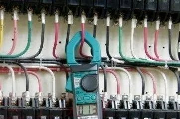
The usage method of the clamp ammeter is simple. As shown in the figure above, to measure current, simply clamp the live wire into the jaws of the clamp ammeter and read the value on the display screen or dial.
It’s quite simple, right? Just clamp the measuring wire. However, with the widespread use of digital clamp ammeters, many multimeter functions have been added, such as voltage, temperature, resistance, etc. (sometimes these multifunctional clamp meters are referred to as clamp multimeters, as shown in the figure above, with two probe sockets on the instrument), and different functions can be selected using a knob, similar to a regular digital multimeter. For specific function buttons, refer to the corresponding manual.
When using a clamp multimeter, pay attention to the following issues:
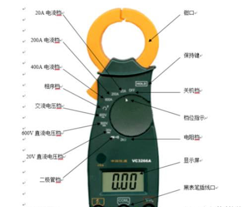
Phase Sequence Testing:
(1) Turn the dial to the phase sequence detection position;
(2) Insert the probes yellow, black, and red into the c, COMb, VΩa sockets respectively;
(3) Connect the red, black, and yellow probes to A, B, C (or L1, L2, L3). When connecting the red and black probes, the indicator light glows slightly, and when connecting the yellow probe, the indicator light is on, indicating a positive phase sequence; if the indicator light is off, it indicates a reverse phase sequence;
(4) The phase sequence position can also measure the phase-to-phase voltage.
AC Voltage Measurement:
(1) Turn the dial to the AC voltage position;
(2) Insert the red and black probes into the VΩa, COMb sockets respectively;
(3) Connect the other end of the red and black probes to the measuring point and read the value.
AC Current Measurement:
(1) Select the appropriate current range;
(2) Fully clamp the live wire with the clamp jaws and read the data;
Note that the maximum testing current for this instrument is only 600A, do not test currents exceeding 600A.
DC Voltage Measurement:
(1) Select the appropriate DC voltage range;
(2) Insert the red and black probes into the VΩa, COMb sockets respectively;
(3) Connect the other end of the red and black probes to the measuring point and read the value.
Resistance Measurement:
(1) Turn the dial to the resistance position 2kΩ;
(2) Insert the red and black probes into the VΩa, COMb sockets respectively;
(3) Connect the other end of the red and black probes to the measuring point and read the value;
Note: Resistance can only be tested when the power is off.
Line Continuity Measurement:
(1) Turn the dial to the diode position;
(2) Insert the red and black probes into the VΩa, COMb sockets;
(3) Connect the other end of the red and black probes to the measuring point and read the value. If the value is very small and the multimeter emits a “beep” sound, the line is connected; otherwise, if the value shows “1” and the multimeter does not sound, the line is either broken or has a very high resistance.
Note: Line continuity can only be tested when the power is off.
Precautions When Using the Clamp Multimeter:
(1) Before using the digital multimeter, carefully read the user manual to familiarize yourself with the power switch functions and range switching switch, input sockets, probe sockets, and the functions of various keys, knobs, and accessories. Additionally, understand the multimeter’s limit parameters, and be aware of the signs and alarms for overload displays, polarity displays, low voltage displays, and other indicators. Before measuring, carefully check for cracks in the probes, damage to the insulation of the leads, and whether the probes are plugged in correctly to ensure the safety of the operator.
(2) Before each measurement, double-check whether the measurement project and range switch are set correctly, and whether the input socket (or special socket) is correctly selected.
(3) When measuring, the instrument may show fluctuating numbers; wait for the displayed value to stabilize before reading.
(4) Although the digital multimeter has a relatively complete protection circuit, try to avoid operational errors, such as measuring voltage with the current range, measuring voltage or current with the resistance range, or measuring charged capacitors with the capacitance range, to prevent damage to the instrument.
(5) If only the highest digit shows “1” and the others are blank, it indicates that the instrument has overloaded, and a higher range should be selected.
(6) Do not switch the range switch while measuring voltages above 10OV or currents above 0.5A to avoid arcing and burning the contacts of the switch.
(7) The numbers next to the dangerous marking on the input socket indicate the maximum input voltage or current for that socket. Exceeding this may damage the instrument and even endanger the operator’s safety.
(8) The clamp multimeter must not be used to measure current in high-voltage lines; the voltage of the measured line must not exceed the voltage rating specified for the clamp meter (generally not exceeding 500 volts) to prevent insulation breakdown and electric shock.
(9) When measuring, estimate the size of the current to be measured and select the appropriate range; do not use a small range to measure large currents.
(10) Before measuring, ensure that the range switch is set to the corresponding AC current range; do not use the voltage or resistance range to measure current.
Remember! Never use the resistance range and current range to measure voltage; if done accidentally, it will burn out the meter.
(11) Only one wire can be clamped at a time during measurement. When measuring, the wire being tested should be placed in the center of the clamp jaws to improve measurement accuracy. It is best to hold the meter body level with your hand, avoiding contact between the wire and the clamp jaws or the meter body.
(12) After measuring, the range switch must be turned to the maximum voltage range, and then the power switch should be turned off to ensure safe use next time.
Disclaimer: The articles uploaded on this WeChat public account only represent the author’s views, and the copyright belongs to the original author. If there are any issues with the source of the article or copyright, please notify us, and we will delete it promptly.
Contact Unit: China Power Equipment Management Association Secretariat
Contact Number: 13911247939
Email: [email protected]

[Long press the fingerprint – Recognize the QR code in the image – Follow us]