Click ↑ for automotive repair cases and follow for updates to obtain the complete timing guide
Highly versatile, applicable to all circuit boards!
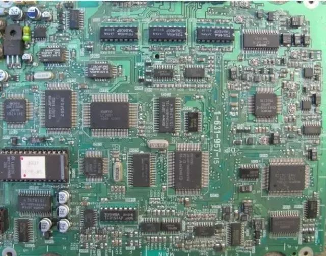
1. How to repair circuit boards without schematics?
1. You must have a clear mental image.
You need to thoroughly understand the principles of some typical circuits and be very familiar with them. Schematics are static, but the ideas in your mind are dynamic; you can make analogies, reason, and apply knowledge from one situation to another. For example, switching power supplies always involve oscillation circuits, switching transistors, and switching transformers. When checking, you need to see if the circuit is oscillating, if the capacitors are damaged, and if the transistors and diodes are functioning properly. Regardless of the type of switching power supply you encounter, the operation is generally similar, and you don’t necessarily need a schematic. For microcontroller systems, including crystal oscillators, three buses (address, data, control), and input/output interface chips, the repair process also revolves around these components. Similarly, for various operational amplifiers in analog circuits, despite their many variations, you can reason based on the principles of ‘virtual short’ and ‘virtual open’ to analyze and clarify the issues. Once you develop good analytical and reasoning skills, even if you encounter equipment you’ve never seen before, you can understand it based on its principles.
2. You must pay attention to the order of repairs.
Following a repair sequence can help you find the shortest path to a solution, avoiding random disassembly that could worsen the faults. Repairing is like a doctor diagnosing a patient; it involves ‘observation, inquiry, examination, and diagnosis.’ ‘Observation’ means checking the appearance of the faulty board for obvious damage, burnt components, or corrosion that could cause broken connections or leakage. ‘Inquiry’ is crucial; you should ask the user detailed questions about the circumstances when the device failed to infer possible faulty components. ‘Examination’ involves using certain testing instruments and methods, checking the resistance, voltage, and waveforms of circuit components under powered and unpowered conditions, comparing good and bad circuit boards, and observing parameter differences.
In fact, many faults can be resolved without even using a multimeter, making schematics unnecessary.
3. Be adept at summarizing patterns.
After accumulating a certain amount of repair experience, you should be able to analyze the reasons for component failures: was it due to improper operation? Lack of maintenance? Poor design? Inferior component quality? Natural aging? With this analysis, when you encounter similar faults in the future, even if the circuit boards are not identical, you will have some understanding. For example, I once encountered an intermittent fault in a Cincinnati machining center. The supplier tried reinstalling the software, reducing harmonic interference, and even disassembling all the boards to replicate the fault on other machines, but after a month, they still couldn’t resolve the issue. Having repaired many computer motherboards, I found that intermittent faults often stem from aging capacitors, so I replaced all the capacitors on the control board, and the problem was resolved in just one hour.
4. Be resourceful in finding information.
Since the advent of the internet, finding information has become very easy. You can almost find the principles of any device or circuit online. Previously, learning depended on a mentor’s willingness to teach. Now, with the internet, your mentors are everywhere in the world, and there are experts in every field. Of course, if your education level is low, language can be a barrier; many resources are in English, such as IC datasheets. However, with tools like Kingsoft PowerWord, if you have a basic understanding of the field, you can often guess and understand most things. With useful information, not having a schematic is not a big deal.
5. You need the necessary testing equipment.
If you consider repair as your career, investing in certain equipment is essential. A soldering iron, multimeter, and common disassembly tools are necessary, and they shouldn’t be of poor quality (I use a FLUKE 189 multimeter that costs over 4000 yuan, haha!). If conditions allow, get a 100M dual-trace oscilloscope, and if possible, an online maintenance testing instrument.
2. Characteristics and repair of capacitor failures in industrial control circuit boards
Capacitor failures are the most common faults in electronic devices, especially with electrolytic capacitors.
Capacitor failures manifest as: 1. Reduced capacitance; 2. Complete loss of capacitance; 3. Leakage; 4. Short circuit.
The role of capacitors in circuits varies, leading to different fault characteristics. In industrial control circuit boards, digital circuits dominate, and capacitors are mostly used for power filtering, with fewer used for signal coupling and oscillation circuits. If an electrolytic capacitor in a switching power supply fails, the power supply may not oscillate and produce no voltage output; or the output voltage may be poorly filtered, causing logic confusion due to unstable voltage, resulting in intermittent operation or failure to start. If the capacitor is between the positive and negative terminals of the digital circuit’s power supply, the fault manifests similarly. This is particularly evident in computer motherboards, where many computers exhibit intermittent startup issues after a few years. Upon opening the case, you often find bulging electrolytic capacitors. If you remove the capacitor and measure its capacitance, it is often significantly lower than its rated value.
The lifespan of a capacitor is directly related to the ambient temperature; the higher the temperature, the shorter the lifespan. This rule applies not only to electrolytic capacitors but also to other types. Therefore, when searching for faulty capacitors, focus on those near heat sources, such as near heat sinks and high-power components, as the closer they are, the more likely they are to fail. I once repaired a power supply for an X-ray inspection machine where the user reported smoke coming from the power supply. Upon opening the case, I found a 1000uF/350V capacitor leaking a viscous substance. After removing it, I measured its capacitance and found it only had a few tens of uF, and it was the only capacitor closest to the heat sink of the rectifier bridge, while others further away were intact and functioning normally. Additionally, ceramic capacitors can also short circuit when located near heat sources. Therefore, focus your inspection accordingly.
Some capacitors leak significantly, and touching them can even cause burns; such capacitors must be replaced.
When troubleshooting intermittent faults, if you have ruled out poor connections, most of the time, the issue is caused by faulty capacitors. Therefore, when encountering such faults, you can focus on checking the capacitors, and replacing them often yields surprising results (of course, also pay attention to the quality of the capacitors; choose reputable brands like Rubycon or Nichicon).
3. Characteristics and identification of resistor failures
Many beginners often struggle with resistors during circuit repairs, disassembling and soldering them repeatedly. However, with experience, you will understand the characteristics of resistor failures, and you won’t need to go through so much trouble.
Resistors are the most numerous components in electrical devices, but they are not the most failure-prone. Resistor failures are most commonly open circuits, with increased resistance being less common and decreased resistance being very rare. Common types include carbon film resistors, metal film resistors, wire-wound resistors, and fusible resistors. The first two types are the most widely used, and their failure characteristics are that low resistance (below 100Ω) and high resistance (above 100kΩ) have higher failure rates, while mid-range resistances (like a few hundred ohms to tens of kilohms) rarely fail. When low resistance resistors fail, they often burn and turn black, making them easy to identify, while high resistance resistors rarely show visible signs of damage. Wire-wound resistors are generally used for high current limiting and have low resistance values. When cylindrical wire-wound resistors fail, some may turn black or show surface peeling or cracking, while others may show no visible signs. Cement resistors, a type of wire-wound resistor, may break when burned, otherwise showing no visible signs. When fusible resistors fail, some may have a piece blown off the surface, while others may show no signs, but they will never turn black. Based on these characteristics, you can focus your inspection on quickly identifying faulty resistors.
Based on the characteristics listed above, we can first observe whether there are any blackened low resistance resistors on the circuit board. Then, based on the fact that most resistor failures are open circuits or increased resistance, and that high resistance resistors are prone to failure, we can use a multimeter to measure the resistance across the terminals of high resistance resistors directly on the circuit board. If the measured resistance is significantly higher than the rated value, that resistor is definitely faulty (be careful to wait for the resistance reading to stabilize before concluding, as there may be parallel capacitive elements in the circuit that cause a charging and discharging process). If the measured resistance is lower than the rated value, it is generally not a concern. By measuring each resistor on the circuit board, even if you ‘wrongly kill’ a thousand, you won’t miss one.
4. Methods for determining the quality of operational amplifiers
Determining the quality of operational amplifiers can be challenging for many electronic repair technicians, not only due to educational background (I have many undergraduates who won’t understand without teaching, and even after teaching, it takes a long time for them to grasp. I also have a graduate student who specializes in variable frequency control, and he is similarly challenged!). Here, I hope to discuss this with everyone and provide some help.
An ideal operational amplifier has the characteristics of ‘virtual short’ and ‘virtual open,’ which are very useful for analyzing linear applications of op-amp circuits. To ensure linear operation, the op-amp must work in a closed-loop (negative feedback) configuration. If there is no negative feedback, the op-amp in open-loop gain becomes a comparator. To determine the quality of the device, you should first clarify whether the device is used as an amplifier or as a comparator in the circuit.
From the diagram, we can see that regardless of the type of amplifier, there is a feedback resistor Rf. Therefore, when repairing, we can check this feedback resistor on the circuit. Use a multimeter to measure the resistance between the output and the inverting input. If the resistance is excessively high, such as several MΩ, we can be fairly certain that the device is used as a comparator. If this resistance is relatively low (0Ω to several tens of kΩ), check if there is a resistor connected between the output and the inverting input; if so, it is definitely used as an amplifier.
According to the principle of virtual short in amplifiers, if this operational amplifier is functioning normally, the voltages at the non-inverting and inverting inputs must be equal, with any difference being in the millivolt range. Of course, in some high input impedance circuits, the internal resistance of the multimeter may slightly affect the voltage measurement, but generally, it should not exceed 0.2V. If there is a difference greater than 0.5V, the amplifier is definitely faulty! (I use a FLUKE 179 multimeter).
If the device is used as a comparator, the non-inverting and inverting inputs are allowed to be unequal.
If the non-inverting voltage > inverting voltage, the output voltage approaches the positive maximum value;
If the non-inverting voltage < inverting voltage, the output voltage approaches 0V or the negative maximum value (depending on whether it is dual-supply or single-supply).
If the detected voltage does not conform to this rule, the device is definitely faulty!
This way, you don’t need to use substitution methods or remove the chips from the circuit board to determine the quality of the operational amplifier.
5. A small trick for testing SMT components with a multimeter
Some surface-mounted components are very small, making it inconvenient to test them with a regular multimeter probe; it is easy to cause short circuits, and it is difficult to contact the metal parts of the component leads on insulated circuit boards. Here, I will share a simple method that will make testing much easier.
Take two of the smallest sewing needles, (Deep Industrial Control Maintenance Technology Column) press them against the multimeter probes, then take a thin copper wire from a multi-strand cable, and use the thin copper wire to bind the probes and needles together, securing them with solder. This way, you can use the probes with fine needle tips to test SMT components without the risk of short circuits, and the needle tips can pierce the insulating coating to access critical areas without the hassle of scraping off the coating.
6. Repair methods for short circuit faults in common power supplies on circuit boards
When repairing circuit boards, encountering short circuit faults in common power supplies can be daunting because many components share the same power supply, and each component using this power supply is a suspect for short circuits. If there are few components on the board, using a ‘ground search’ method can eventually locate the short circuit point. However, if there are too many components, relying on luck may not yield results. Here, I recommend a relatively effective method that can often quickly identify the fault point.
You need a power supply that can adjust both voltage and current, with a voltage range of 0-30V and a current range of 0-3A. This power supply is inexpensive, around 300 yuan. Set the open-circuit voltage to the device’s power supply voltage level, first adjusting the current to the minimum. Apply this voltage to the power supply points of the circuit, such as the 5V and 0V terminals of 74 series chips. Depending on the severity of the short circuit, gradually increase the current. When you feel a component heating up significantly, that is often the damaged component, which you can then remove for further measurement and confirmation. Of course, during operation, the voltage must not exceed the working voltage of the components, and it must not be reversed; otherwise, other good components may be damaged.
7. A small eraser can solve big problems
With the increasing use of industrial control boards, many boards use gold fingers inserted into slots. Due to harsh industrial environments—dusty, humid, and corrosive gases—these boards can develop contact faults. Many friends may have solved the problem by replacing the boards, but the cost of purchasing boards can be quite substantial, especially for certain imported equipment. In fact, you might try using an eraser to clean the gold fingers by rubbing them several times to remove dirt, and then test the machine again; you might just solve the problem! This method is simple and practical.
8. Analysis of intermittent electrical faults
Various intermittent electrical faults can be categorized by probability as follows:
1. Poor connections
Poor contact between the board and the slot, internal breaks in cables, poor contact at connectors and terminals, and cold solder joints all fall into this category;
2. Signal interference
For digital circuits, faults may only manifest under specific conditions, possibly due to excessive interference affecting the control system, or changes in the parameters of individual components or overall performance approaching critical points, leading to faults;
3. Poor thermal stability of components
Based on extensive repair experience, the most common issue is poor thermal stability of electrolytic capacitors, followed by other capacitors, transistors, diodes, ICs, and resistors;
4. Moisture and dust on the circuit board. Moisture and dust can conduct electricity, creating resistance effects, and during thermal expansion and contraction, the resistance can change, which can have a parallel effect with other components, significantly altering circuit parameters and causing faults;
5. Software is also a consideration.
Many parameters in circuits are adjusted using software, and if certain parameters are set too close to their limits, when the machine operates under conditions that meet the software’s fault criteria, alarms will trigger.
9. How to quickly find component information?
Modern electronic products are diverse, and the variety of components is increasing rapidly. In circuit repairs, especially in the field of industrial circuit board repairs, many components may be unfamiliar or even unheard of. Additionally, even if you have complete information on the components of a particular board, if you have to sift through this information on a computer without a quick search method, repair efficiency will significantly decrease. In industrial electronic repairs, efficiency is money; compromising efficiency is compromising your wallet.
We should be grateful to live in this great era where the internet is boundless, making every corner of the world seemingly within reach, with free information available everywhere. So, everyone should make good use of the internet as a powerful tool to make your work easier! Finally, I wish everyone smooth repairs and success in every task. Haha…
Tire Master: dashiluntai