Many beginners encounter this challenge when working on projects: a temperature sensor measures 25°C, and a pressure sensor measures 3.5MPa. How do these “continuously varying numbers” get transmitted to the PLC? How does the PLC “understand” these signals?
In fact, these “continuously varying quantities” are called “analog signals,” which are different from discrete signals (on/off). Today, I will explain in simple terms how to read analog signals with Mitsubishi PLCs, teaching beginners step by step from “wiring” to “programming”!
First, let’s understand: What is an analog signal? How does it differ from a discrete signal?
The X0, Y0 we learned before are “discrete signals”—either on (1) or off (0), like buttons and contactors.
On the other hand, an “analog signal” is a continuously varying value, for example:
– Temperature: 20°C→25°C→30°C (gradually increasing);
– Pressure: 1MPa→2MPa→3MPa (gradually increasing);
– Speed: 1000 RPM→1500 RPM→2000 RPM (continuously changing).
These signals cannot directly enter the PLC’s standard input port (X); they require an “analog module” (such as Mitsubishi FX3U-4AD) to act as a “translator,” converting the sensor signals into numbers that the PLC can understand.
Signal Types of Analog Sensors: Two Common Types
The signals sent from the sensors to the analog module are like “codes,” and there are two common types:
1. Current Signal (4~20mA)
Strong anti-interference capability, suitable for long-distance transmission (for example, from the workshop to the control room, several dozen or even hundreds of meters). For instance, when a pressure sensor measures 0~10MPa, it corresponds to an output of 4mA~20mA (0MPa→4mA, 10MPa→20mA).
2. Voltage Signal (0~10V or -10V~+10V)
Simple wiring, but weaker anti-interference, suitable for short distances (within a few meters). For example, when a temperature sensor measures 0~100°C, it corresponds to an output of 0V~10V (0°C→0V, 100°C→10V).
Remember: The signal type of the sensor must match the analog module (if the module supports current, connect current; if it supports voltage, connect voltage).
Analog Signal Processing Steps
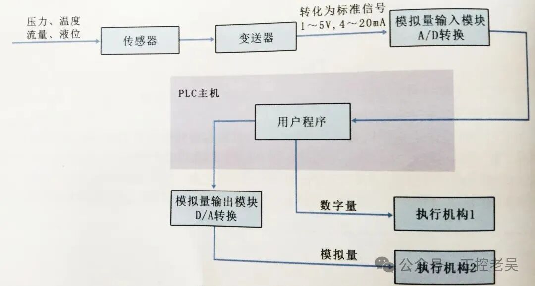 1. The collection of analog signals is completed by the sensor. The sensor converts non-electrical signals (such as temperature, pressure, liquid level, flow, etc.). Note that at this point, the electrical signal is a non-standard signal. 2. The non-standard signal is converted into a standard electrical signal, a task performed by the transmitter. The non-standard electrical signal output by the sensor is sent to the transmitter, which converts it into a standard electrical signal. According to international standards, standard electrical signals are divided into voltage type and current type. The voltage standard signals are DC0-5V and DC0-10V, while the current standard signals are DC0-20mA and DC4-20mA. 3. A/D conversion and D/A conversion. After the transmitter sends its output standard signal to the analog input module, the analog input module converts the analog signal into a digital signal. The PLC processes this signal, and its output can either drive an output relay to control a discrete load or, after D/A conversion through an analog output module, output an analog signal to control an analog load.
Three Steps to Read Analog Signals with Mitsubishi PLC: Wiring → Settings → Programming
Taking the “FX2U-4AD” module (4-channel analog input) and a “0~10V voltage-type temperature sensor (0~100°C)” as an example, let’s see how to get the PLC to read the actual temperature.
Step 1: Wiring—Connect the Sensor to the Analog Module
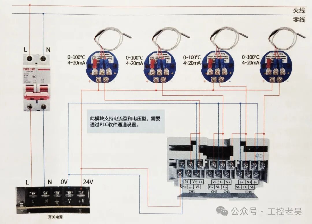
1. Connect the sensor’s “signal+” to the module’s “V+” (for example, channel 1’s V1+);
2. Connect the sensor’s “signal-” to the module’s “V-” (for example, channel 1’s V1-);
3. Provide power to the sensor from the module’s “24V” and “0V” (if the sensor requires external power).
Step 2: Set Module Parameters—Inform the Module of the “Signal Type”
The module may not default to “0~10V” and needs to be set using software (such as GX Works2):
1. Open the software and find “Analog Module Settings” in the “Parameters”;
2. Select the “Position” of the module (for example, the first module to the right of the FX2U host, set the position to “1”);
3. Set the “Input Type” of channel 1 to “0~10V”.
Step 3: Programming—Use Instructions to Convert the “Raw Value” to Actual Temperature
The module will convert the 0~10V voltage signal into a “raw value” (for example, 0~4000):
0V→0;
10V→4000;
5V→2000 (proportional changes in between).
We need to use the “FROM instruction” to read this raw value into a register D, and then convert it to the actual temperature (0~100°C).
Programming Steps:
1. Use the special function read instruction (FROM instruction) to read the raw value of channel 1:
“FROM K1 K0 D10 K1”
(K1=module position, K0=channel 1, D10=register to store raw value)
→ For example, when the sensor measures 25°C, it outputs 2.5V, and the module will convert 2.5V to 1000, storing it in D10.
2. Convert to actual temperature:
Since 0~4000 corresponds to 0~100°C, the temperature = (D10 value ÷ 4000) × 100
Using the division instruction “DIV D10 K40 D20” (D20=D10÷40), then multiply by 100 → actually simplifies to D10÷40, for example, D10=1000→1000÷40=25°C.
Two Common Pitfalls for Beginners
1. Incorrect readings? Check wiring and parameters first
Incorrect wiring (signal +/- reversed) will read 0 or negative values;
Incorrect module parameters (for example, if the sensor is 0~10V, but the module is set to 4~20mA) will cause value deviations.
2. Large value fluctuations? Add filtering
Analog signals are easily affected by interference; if readings fluctuate significantly, add “filtering” to the channel in the module parameters (for example, set the filtering level to “medium”) to stabilize the values.
Summary: The Process of Reading Analog Signals
1. Connect the sensor (0~10V/4~20mA) to the analog module (such as 4AD);
2. Set the module’s position and signal type in the software;
3. Use the FROM instruction to read the raw value into D;
4. Convert proportionally to the actual physical quantity (temperature/pressure, etc.).
By learning to read analog signals, the PLC can “perceive” changes in the world, upgrading from “switch control” to “precise adjustment” (for example, automatically stabilizing the temperature at 25°C).
What analog sensors have you used? Have you encountered issues with inaccurate readings? Share your solutions in the comments! Like and follow for the next topic on “How PLC Outputs Analog Signals (Controlling Inverter Speed)!”😉
The D register of Mitsubishi PLC: A “data piggy bank” that beginners can understand.
How to use Mitsubishi PLC comparison instructions? A “digital judgment” technique that beginners can learn.