Click the blue text
Follow us
Special Topic on Electric Control Technology
“Industry + Technology + Talent”
Special Topic on PLC Control Technology
Tech.
Part.1
PLC Control Technology
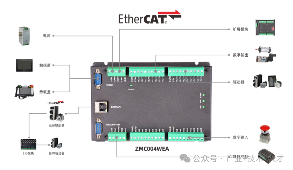
PLC controllers are applied in almost all fields requiring automated control, involving:core control technologies (logic control, sequential control, process control, motion control, data acquisition and processing),communication and network technologies,programming and software technologies,safety technologies, andsystem integration technologies. The platform shares technical insights on PLC control.
Part.04
PLC Control | Counter
Today we will delve into the functions and types of PLC counters. Counters are fundamental functional modules in PLCs, equally important as timers, and are indispensable for achieving automated production.
1. Core Functions of PLC Counters
The core function of a counter is to count internal or external pulse signals, executing specific control actions when the count reaches a preset value.
In simple terms, it is an “electronic counter” or “event recorder”.
Without counters, PLCs cannot achieve any automation control related to quantity.
2. Working Principles and Key Elements of Counters
To understand counters, one must grasp the following key elements:
-
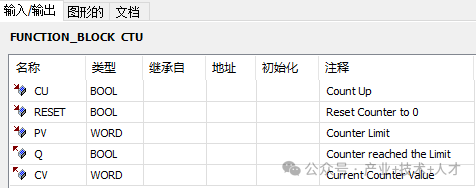
Count Pulse (CU): This is the “input signal” for the counter. The counter detects therising edge or falling edge of this signal, not the signal level itself. This is crucial for accurate counting (each valid physical event corresponds to one edge, avoiding double counting).
-
Preset Value (PV): The target count value you want the counter to reach.
-
Current Value (CV): The real-time value recorded by the counter.
-
Reset Signal (RESET): Used to clear the current value of the counter to zero. This signal usually has the highest priority; once valid, the counter resets immediately.
-
Output Signal (Q):
Basic workflow (taking an up-counter as an example): Detecting a count pulse rising edge → Current value +1 → Current value ≥ Preset value → Counter outputs action
3. Main Types of Counters and Detailed Functions
Based on counting direction and working methods, counters are mainly divided into the following three basic types:
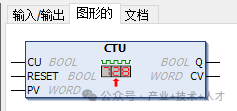
1. Up Counter (CTU)
-
Function metaphor: “A calculator that accumulates positively”.
-
Working Principle:
-
Each time arising edge pulse reaches the counting input, the current value of the counter increases by 1.
-
When the current value is greater than or equal to the preset value, the output contacts of the counter act (normally open contacts close, normally closed contacts open).
-
Regardless of whether the current value reaches the preset value, as long as the reset signal is valid (RESET=1, i.e., high-level pulse signal), the counter immediately resets (the current value (CV) is cleared to zero, and the output contacts (Q) return to their initial state).
-
Timing Diagram:
Count Pulse (CU): __|‾|__|‾|__|‾|__|‾|__|‾|__ (each rising edge counts once)
1 2 3 4 5
Current Value (CV): 0 ->1 ->2 ->3 ->4 ->5 … (assuming preset value=4)
Output Signal (Q): ____________________| |______ (Q outputs ON when current value ≥ 4)
Reset Signal (RESET): _______________________| |__ (current value cleared, output OFF)
-
Typical Applications:
-
Product Quantity Statistics: Each time a photoelectric sensor detects a product, it sends a pulse, and the counter increments by 1. After reaching the quantity for a full box, it starts the packaging machine and resets the counter.
-
Assembly Line Station Control: Every 5 workpieces, the robotic arm performs a grabbing action.
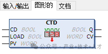
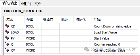
2. Down Counter (CTD)
-
Function metaphor: “Countdown timer”.
-
Working Principle:
-
The counter must first beloaded, meaning its current value is set to the preset value.
-
Each time arising edge pulse reaches the counting input, the current value of the counter decreases by 1.
-
When the current value decreases to less than or equal to 0, the output contacts of the counter act.
-
When the load signal is valid, the preset value is loaded back into the current value.
-
Timing Diagram:
Load Signal (LOAD) ______| |____________(loads preset value PV into current value CV)
Current Value (CV) : 4 ->4 ->3 ->2 ->1 ->0 (assuming preset value PV=4)
Count Pulse (CD): ______|‾|__|‾|__|‾|__|‾|______ (each rising edge, CV decreases by 1)
(CV<=0, output ON)
Output Signal (Q): _______________________| |____
-
Typical Applications:
-
Quantitative Loading: Set the quantity to be filled (preset value), and each time a material is loaded, it decreases by 1, stopping when it reaches 0.
-
Batch Control on Production Line: Set a batch quantity, and each time a product is produced, it decreases by 1, indicating that the batch production is complete when it reaches 0.
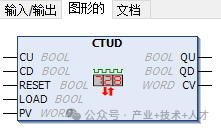
3. Up/Down Counter (CTUD)
-
Function metaphor: “A bidirectional counter that can both add and subtract”.
-
Working Principle:
-
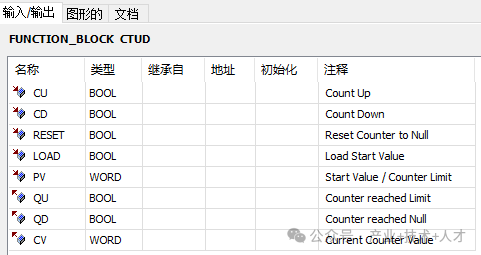
It has two counting input terminals:up counting terminal and down counting terminal.
-
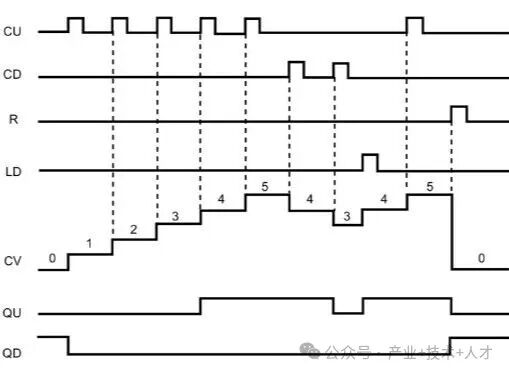
On the rising edge of the up counting terminal, the current value increases by 1; on the rising edge of the down counting terminal, the current value decreases by 1.
-
It also has a reset terminal to clear the current value CV to zero.
-
When the current value is greater than or equal to the preset value, the output contacts act.
-
Timing Diagram:
Typical Applications:
-
Warehouse Material Statistics: When materials are stored, the up counting terminal increments by 1 with each pulse from the storage sensor; when materials are shipped, the down counting terminal decrements by 1. The current value reflects the inventory quantity in real-time.
-
Parking Lot Vehicle Counting: The entrance barrier machine signal triggers up counting, while the exit triggers down counting, with the current value indicating the remaining parking spaces.
*Notes on Using Counters:
1, The execution conditions of timers are related to the conditions that trigger them; each type of timer is slightly different, but the principles are similar. When the trigger terminal is scanned, it determines whether the timer starts, stops, or continues counting.
2, To effectively use timers, one must considerthe characteristics of the timer and the order of program instruction execution, ensuring that there is sufficient time for the program to capture the moment the timer finishes counting before the next call to the timer in the program.
3, When programming, one must consider not only the logic but also the operation mode of the timer and the timing of action triggers, to better utilize the timer for the program.
*Tips for Using Counters:
1, You can call adelay block after the timer to extend the effective time of the timer’s output, increasing the probability.
2, Under the premise of meeting logical requirements, operations on the timer’s nodes can be placed before the timer (e.g.,SD), which can also increase the effective time of the timer’s output to some extent.
3, If the program only involves some logical processing without specific timing requirements, set the timer’s time as small as possible to increase the probability in absolute time.
4, For parts of the program that cannot be confirmed, you can first run thePLCSIM simulator to see if any unknown situations occur.
If there are any errors or deficiencies in the above content, please point them out, thank you very much!
►►►
Previous Reviews
PLC Controller | Programming | Electrical Control | Series Courses
PLC Control Series | New Project | Joint Debugging | CODESYS
PLC Control Series | Digital | Analog | Configuration
Electric Control Technology | PLC Control | Timer

Platform Statement
Statement: All articles, images, audio, video files, and other materials reproduced by this public account are owned by the copyright holders. The non-original articles and images used by this public account cannot be contacted with copyright holders one by one. If the authors and editors of the selected content believe that their works should not be published for readers to browse, or should not be used free of charge (involving cost issues, need to delete “not suitable for online browsing or should not be used free of charge”), please promptly notify us via email or phone, so that we can take appropriate measures quickly to avoid unnecessary economic losses for both parties.
END


FOOL‘S DAY


FOOL‘S DAY


Douyin Account丨61954232067

FOOL‘S DAY
Bilibili丨505216210


Earth Day
WeChat ID丨15327052487
Bilibili Account丨Industry Technology Talent