In the previous chapter, we configured the Hrtime TA TB output complementary PWM output. In this section, we will configure the use of TA CH3 channel to trigger ADC sampling. The MCU used is GD32F334.1. ADC Configuration2.1 ADC1 Mode Configuration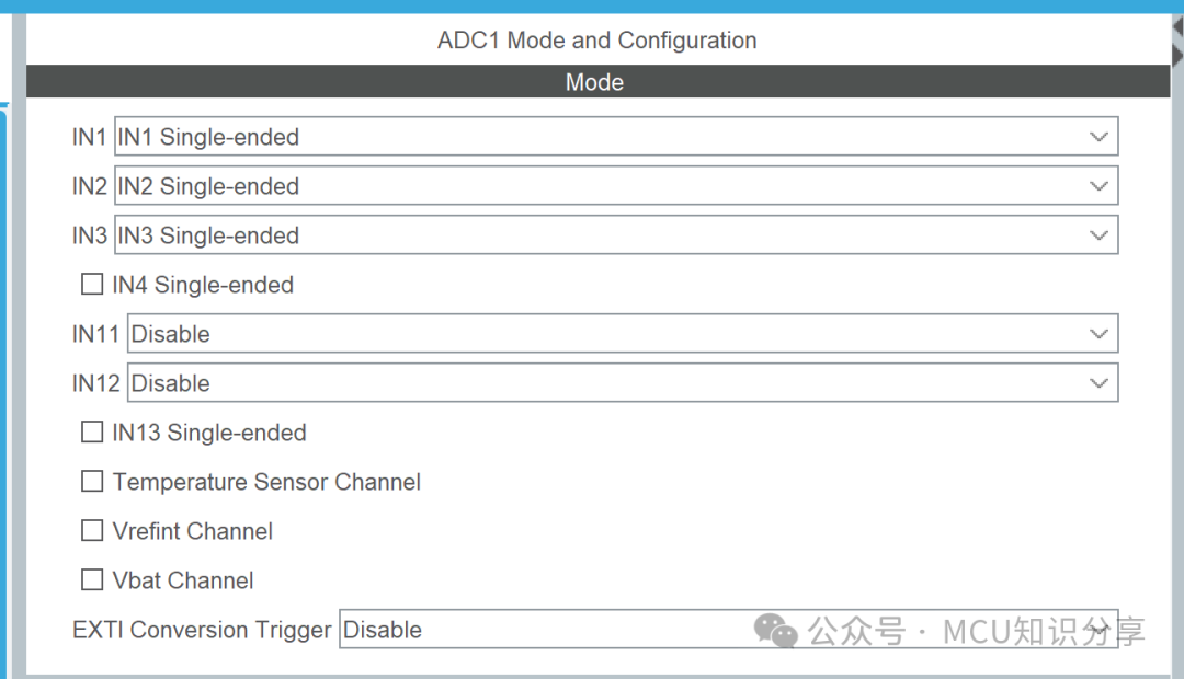 Enable ADC1 channels 1, 2, and 3.
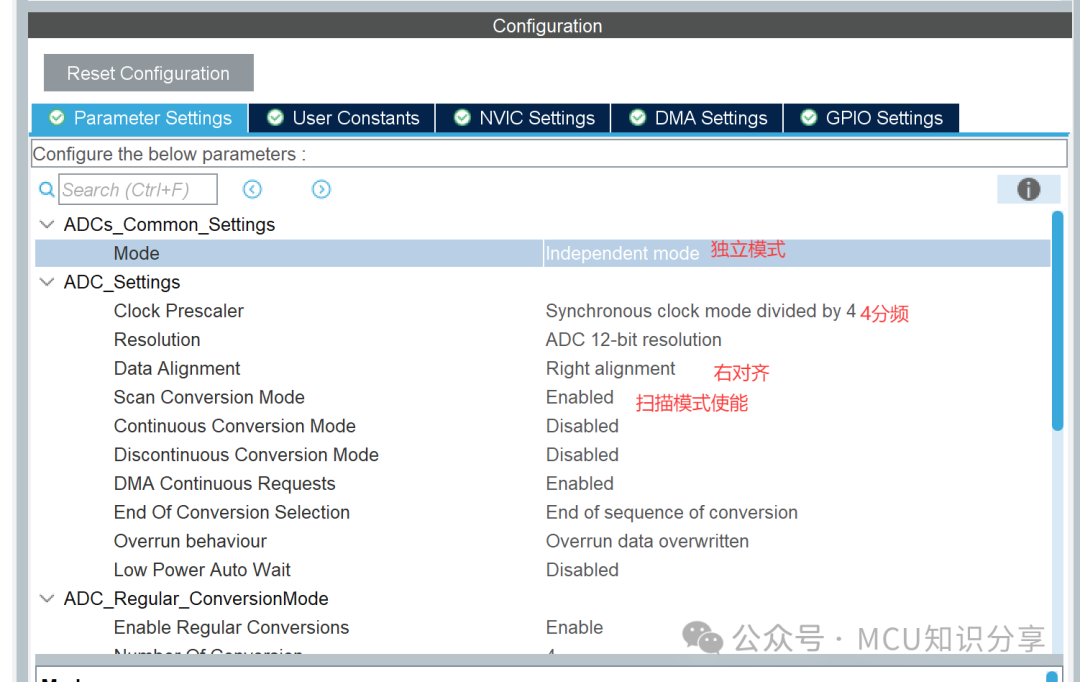 Clock Prescaler: The clock division, the main clock is divided to provide the ADC clock.Resolution: The resolution of the MCU ADC is divided into 6-bit, 8-bit, and 12-bit; here we choose 12-bit. For example, with a voltage of 3.3V and a 12-bit resolution, it divides 3.3V into 4096 parts (2^12).Data Alignment: The data alignment method, which can be left-aligned or right-aligned.Scan Conversion Mode: Scans the channels for ADC sampling based on the order set by the channels.Continuous conversion mode and discontinuous conversion mode: In continuous conversion mode, after a group of ADC conversions is completed, it can continue to start conversions without requiring a trigger source intervention. When disabled, the conversion stops after a group is completed and must wait for the next trigger to start conversion.DMA Continuous Requests: DMA transfer mode, transferring ADC data to a specified storage area via DMA channel.End of Conversion Selection: ADC conversion end flag.Overrun Behaviour: Overrun method, when the ADC’s DR register already contains the data from the last conversion and has not been read, and another ADC channel conversion is completed, this option allows you to choose whether to keep the previous data or overwrite it with the new data.Overrun data overwritten.Low Power Auto Wait:Do not perform conversion at low voltage, wait for voltage recovery.
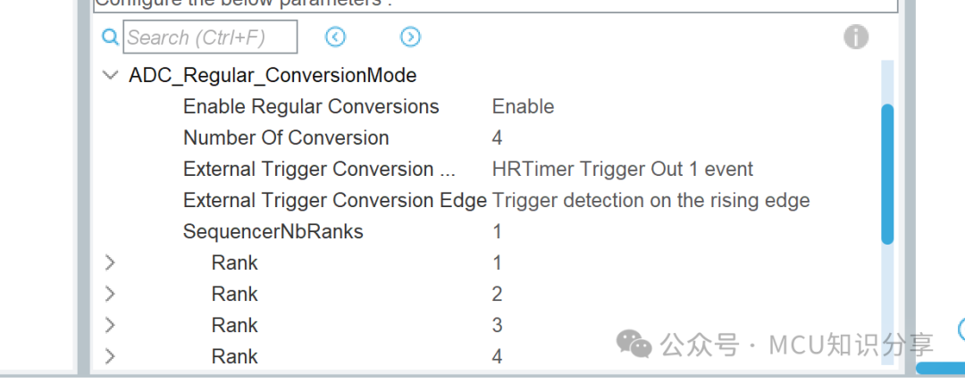 ADC Regular Group Conversion ModeEnable Regular Conversions: Enable ADC regular group conversions.External Trigger Conversion Source: External trigger source.External Trigger Conversion Edge: The triggering method of the external source, which can be rising edge or falling edge.
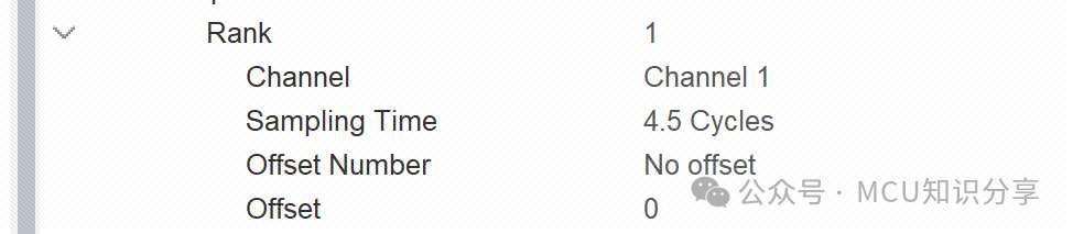 Set the conversion time for the corresponding group channels.2. DMA Configuration
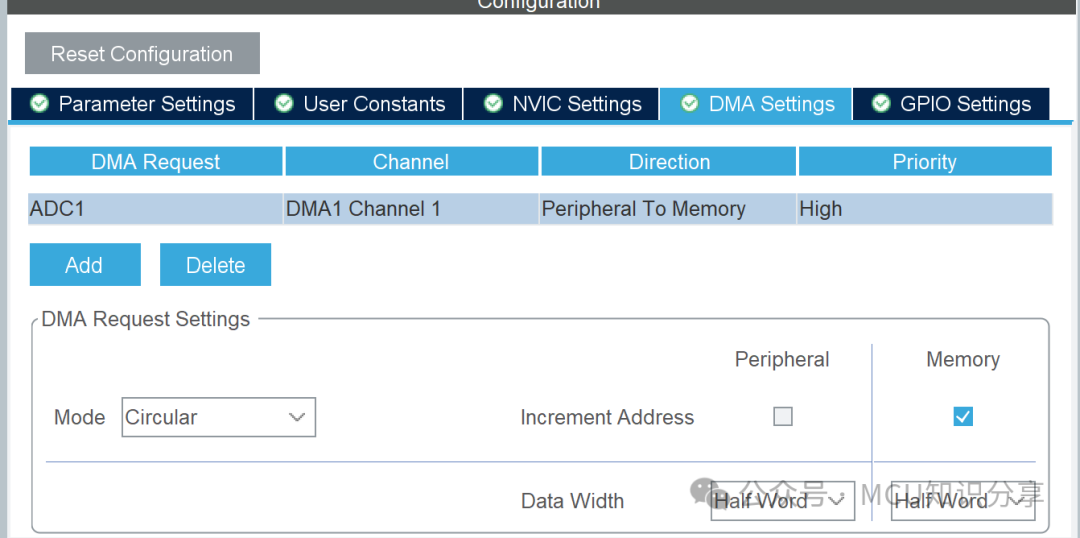 Mode (Request Mode): You can choose single or circular mode. If single is selected, the DMA will stop transferring after one round of data transfer; if circular is selected, it will automatically proceed to the next round of transfer after completing one round of data.2.Hrtime ADC Trigger Configuration
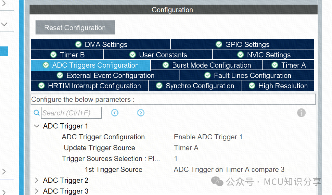 Select ADC Trigger 1, with the trigger source chosen as Timer A.One trigger source is selected, and the first trigger source is set to TIMER A’s third compare channel.
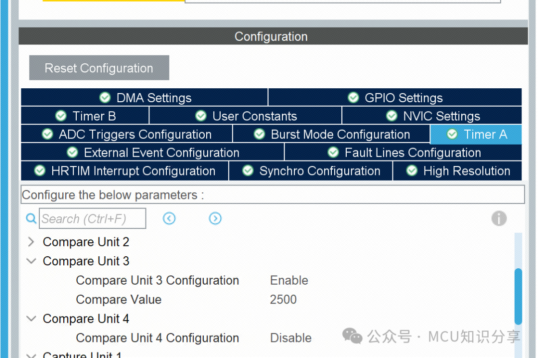 Comparator channel settings, enable it, with a comparison value of 2500.A line of code to start the ADC must be added in the program.
HAL_ADC_Start_DMA(&hadc1, (uint32_t*)ADC1_RESULT, 4);
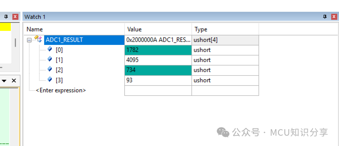
3. Running Effect