The main function of an oscilloscope probe is to bring the voltage signal being measured from the measurement point into the oscilloscope for measurement. Ideally, the oscilloscope probe should have no effect on the measured signal, but in reality, its long cable inevitably has stray inductance, capacitance, and resistance. Therefore, they will affect the oscilloscope’s interpretation of the signal being measured, especially at very high frequencies.
There are various types of probes, with the most commonly used being the passive attenuation probe that comes with most oscilloscopes. It has a large resistor in parallel with a very small capacitor to help reduce the load effect that the long cable of the probe brings to the circuit being measured. This high internal resistance is in series with the input resistance of the oscilloscope, forming a voltage divider for the input signal.
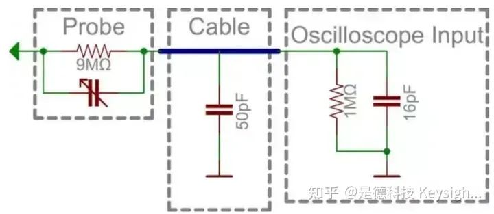
The internal impedance of most oscilloscope probes is a 9MΩ resistor, which is connected to the standard 1MΩ input resistance of the oscilloscope, forming a 1/10 voltage divider. This type of probe is called a 10X attenuation probe. Many probes have a switch that can toggle between 10:1 attenuation (10X) and no attenuation (1X).
Current Probes
An oscilloscope current probe, as the name suggests, displays the current in the conductor rather than the voltage across it when used with an oscilloscope. This type of probe has a current sensing transformer at its head, and during use, it can be clipped onto the cable conductor without cutting the circuit. The signal obtained by the probe is first converted into a voltage and then sent to the oscilloscope after proportional transformation, at which point the oscilloscope displays the unit as A/div or mA/div. The frequency range of the probe can reach over 70MHz.
After using a current probe, an oscilloscope with mathematical processing capabilities can measure power by multiplying the voltage waveform and current waveform. It can also simultaneously perform AC/DC measurements without cutting the circuit. The load is very small.
When current is passed through a semiconductor and placed in a magnetic field, if the magnetic field is perpendicular to the direction of the current, the movement direction of the charge carriers (electrons or holes) will be deflected under the influence of the magnetic field. As a result, charge accumulation will occur in a direction perpendicular to both the current and the magnetic field, creating a potential difference. This phenomenon is called the Hall effect. The Hall effect can be used to create Hall devices, and it can also be used to measure the conductivity type, carrier concentration, and mobility of semiconductor materials.
A current probe can provide clearer current waveform diagrams. It eliminates measurement uncertainties and the need for complex calculations, making measurement, recording, and sharing easier. Depending on its specifications, a current probe can measure any current from very low to very high.
Classification of Oscilloscope Probes
Current Probe Principles
A current probe is an electrical measuring instrument used to measure the magnitude of current in a circuit. They are often quite large and have limited bandwidth (100 MHz). Its principle is based on Faraday’s law of electromagnetic induction, which states that a changing magnetic flux will induce electromotive force in a conductor, thus measuring the current value in the circuit. The following will provide a detailed introduction to the principles of current probes and related knowledge.
The current flowing through a conductor creates an electromagnetic flux field around it, and the oscilloscope current probe measures the magnetic field generated by electrons moving within the conductor. By detecting the changes in the magnetic field, it converts the magnetic field into a corresponding voltage signal, which, when combined with a real-time oscilloscope, provides the corresponding current waveform.
When testing DC and low-frequency AC, the oscilloscope current probe uses Hall devices to detect and measure mixed AC and DC currents utilizing the Hall effect. As the frequency of the current signal being measured increases, the Hall effect gradually weakens. When measuring high-frequency AC currents, a current transformer is used to sense the AC current.
Hall devices detect low-frequency components, while the current transformer coil detects high-frequency components. The two are combined to meet different application scenarios. AC/DC current probes utilize Hall devices to sense DC current and use the current transformer coil to sense AC current, thus completing the detection of both AC and DC currents.
To measure current with an oscilloscope, a current probe is required. The commonly used current probes utilize the Hall effect to measure the magnetic field and obtain the current signal by measuring the changes in the magnetic field around the circuit.
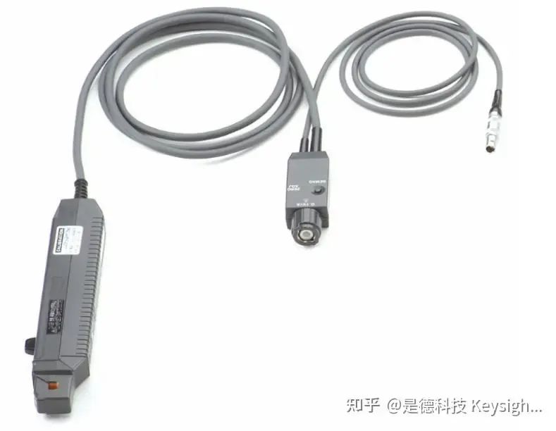
Image of an Oscilloscope Current Probe
In summary, the principle of a current probe is based on Faraday’s law of electromagnetic induction and electromagnetic induction phenomena, utilizing the interaction between the magnetic field and electric grid to generate voltage signals, thereby measuring the magnitude of current in the circuit. In practical use, it is important to ensure measurement accuracy, signal interference, and signal distortion.
What is the Hall Effect?
The Hall effect is a type of electromagnetic effect discovered by American physicist Edwin Hall in 1879 while studying the conductivity mechanism of metals. When current flows through a semiconductor perpendicular to an external magnetic field, the charge carriers are deflected, creating an additional electric field perpendicular to the current and magnetic field, resulting in a potential difference at the ends of the semiconductor. This phenomenon is known as the Hall effect. It can be likened to a road where people are evenly distributed and moving forward; when a magnetic field is present, they might be pushed to the right side of the road, creating a voltage difference on either side of the road (conductor), referred to as the ‘Hall effect.’
Who Needs Current Probes?
The main customers are R&D, maintenance, service, and engineers/technicians. Applications include power supply design and testing, current consumption analysis, and charging systems.
Main Applications of Current Probes
Power device testing and characterization
Switching power supply design and testing
Current loss analysis
High voltage testing
Battery charging systems
Impulse current testing
New energy/hybrid module current testing
IoT module current loss (N2820A/21A)
Two Methods for Measuring DC Current
The first method is to directly use a current probe. Keysight provides various current probes that can test both DC and AC. For higher measurement accuracy, multiple loops of the current-carrying wire can be placed through the hole of the current probe. The second method is to convert the current into voltage. A large high-precision resistor needs to be placed in the measured circuit, and a differential probe measures the voltage across the resistor, which is then converted into current for measurement.
Next, we will specifically introduce techniques for measuring current with an oscilloscope and current probe to improve measurement accuracy.
Engineers often need to perform more sensitive current measurements when designing mobile phones and other battery-powered devices to ensure that the current consumption of the device is within acceptable limits. The process of measuring current can be very cumbersome because you have to interrupt the circuit and connect the measuring instrument in series with the circuit. Using clamp-on current probes and oscilloscopes can easily implement current measurements without damaging the circuit. However, measuring milliamps or smaller currents significantly increases measurement difficulty.
Today, we have introduced several very practical measurement techniques that can help you accurately measure current in high-noise environments with oscilloscopes.
The Impact of Oscilloscope Noise is Important
As the current level decreases, the inherent noise of the oscilloscope becomes a real issue. All oscilloscopes have an excess characteristic—vertical noise. When measuring low-level signals, the noise in the measurement system can lead to decreased accuracy in measuring the actual signal. Since oscilloscopes are broadband measuring instruments, the wider the bandwidth of the oscilloscope, the higher the vertical noise. Therefore, before measuring, you need to carefully test the noise characteristics of the oscilloscope. A 500 MHz bandwidth oscilloscope typically has a background noise of about 2 mV peak-to-peak when set to the most sensitive V/div setting. When performing low-level measurements, it is important to note that the acquisition memory on the oscilloscope may affect the background noise. With all other conditions being equal, the deeper the acquisition memory, the greater the noise. On the other hand, modern AC/DC current probes (such as the Keysight N2783B 100 MHz current probe) can measure AC or DC currents as low as 5 mA, with a measurement accuracy of about 3%. The design of this current probe outputs 0.1 V for every ampere of current input. In other words, when measuring current below 20 mA, the oscilloscope’s 2 mVpp noise may be the primary source of noise.
So, how can you minimize the inherent noise of the oscilloscope?
For modern digital oscilloscopes, there are many methods to choose from:
1) Bandwidth Limiting FiltersMost digital oscilloscopes provide bandwidth limiting filters that can filter out excess noise in the input waveform and reduce noise bandwidth, thereby improving vertical resolution. Bandwidth limiting filters can be implemented in hardware or software. Most bandwidth limiting filters can be enabled or disabled as needed.
2) High-Resolution Acquisition ModeMost digital oscilloscopes provide 8-bit vertical resolution in normal acquisition mode. Some oscilloscopes can offer higher vertical resolution in high-resolution mode, typically up to 12 bits, which can reduce vertical noise and improve vertical resolution. Generally, when applying a slower time/div setting, the number of data points captured on the screen is very high, and at this time, high-resolution mode has a significant impact. Since the acquisition in high-resolution mode averages adjacent data points for a single trigger point, it reduces the sampling rate and bandwidth of the oscilloscope.
3) Average ModeIf the signal is periodic or DC, you can use average mode to reduce the vertical noise of the oscilloscope. Average mode captures periodic waveforms multiple times and generates running averages to reduce random noise. High-resolution mode reduces the sampling rate and bandwidth of the signal, while normal average mode does not. However, average mode will slow down the waveform update rate because it must capture multiple times to calculate the average waveform before plotting it on the screen. When you select a large number of averages, the noise reduction effect is more significant than any of the above methods.
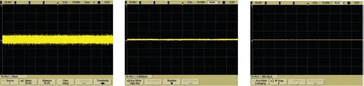
Figure 1. There are many ways to reduce the inherent vertical noise of the oscilloscope.
How to Improve the Measurement Accuracy and Sensitivity of Current Probes?
Now that you understand how to use any of the above techniques to reduce the vertical noise of the oscilloscope, let’s take a look at how to improve the accuracy and sensitivity of current probes. There are many types of current probes on the market. The most convenient and high-performing type is the clamp-on AC/DC current probe, which you can clamp onto the current-carrying conductor to measure AC or DC current. The Keysight N2780A series or 1147B current probes are typical representatives of this type of probe.
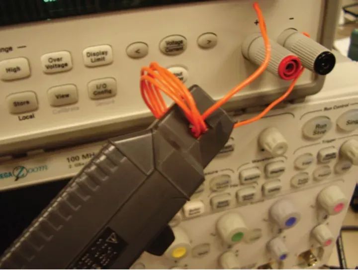
Improving the accuracy of current probes through demagnetization and DC offset
Improving the sensitivity of the probe by winding multiple loops of the conductor being measured
Techniques for Using Current Probes
1. Eliminate Magnetism (Demagnetize) and DC Offset
To ensure accurate measurement of low-level currents, you need to demagnetize the core to eliminate residual magnetism. Just as demagnetizing a CRT display can improve image quality, you can eliminate any residual magnetism by demagnetizing the current probe. If measurements are taken while the probe core is magnetized, a bias voltage proportional to the residual magnetism will be generated, leading to measurement errors. It is crucial to demagnetize the probe core whenever you turn the probe’s power switch on/off or when applying excessive current to its input. To perform demagnetization, you can disconnect the probe from all conductors, ensure the probe is locked, and then press the probe’s DEMAG (or DEGAUSS) button.
Additionally, you can use the zero-adjust control button on the probe to correct for any excess voltage bias or temperature drift.
2. Increase the Sensitivity of the Oscilloscope Probe
The current probe can measure the magnetic field generated by the current flowing through the probe’s jaws. It generates a voltage output proportional to the input current. If you are measuring DC signals or small amplitude low-frequency AC signals, you can increase measurement sensitivity by winding multiple loops of the conductor being measured around the probe. At this time, the signal strength will be multiplied by the number of turns of the conductor wrapped around the probe. For example, if a conductor is wrapped around the probe 5 times and the oscilloscope displays a reading of 25 mA, the actual current is 25 mA divided by 5, which is 5 mA. In this case, you can increase the sensitivity of the current probe by 5 times.
Using clamp-on current probes and oscilloscopes makes it very convenient to measure current without damaging the circuit. However, when introducing the oscilloscope’s broadband noise into the measurement results, the vertical noise of the oscilloscope may hinder precise low-level current measurements. By employing one or more of the measurement techniques introduced in this article, you can eliminate random noise from the oscilloscope as well as excess magnetism or DC offset from the current probe, significantly improving your measurement accuracy.
Source: Keysight Technologies
END
Community Activities
DIY Creative Design Competition for Electronic Engineers
Event Time: 2023.11.1-2023.12.31

Award Setup: First Prize (1): Uni-T UTD1025CL Handheld Digital Storage Oscilloscope/DJI Osmo Action 4 Camera/DJI Mini 2 SE Drone (choose one)
Second Prize (2): One Xiaomi Redmi Pad SE Tablet Third Prize (3): Pro’sKit SS-936H Temperature Controlled Soldering Station Set Participation Prize (10): 100 RMB JD Card (based on the quality and difficulty of the submitted work)