If you do not have a probe, your oscilloscope will be incomplete, as the probe is an essential component that connects the device under test to the oscilloscope. The nature and quality of the probe will affect the accuracy of measurement displays and signal analysis. Probes are crucial for signal integrity, so you must choose carefully to avoid limiting the oscilloscope’s functionality.
Due to the variety of oscilloscopes and probes available, we will use a mixed-signal oscilloscope (MSO) as an example to briefly introduce how to connect an oscilloscope probe. How do you connect a digital probe to the device under test?
1. If necessary, turn off the power of the device under test.
Turning off the power of the device under test can only prevent damage that may occur due to accidental short circuits between the two power lines when connecting the probe. Since there is no voltage display on the probe, the oscilloscope can remain powered on.
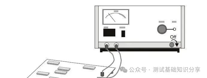
Note: Be careful with the digital channel probe cable – only use the Keysight logic probe and accessory kit that comes with the mixed-signal oscilloscope.
2. Connect the digital probe cable to the DIGITAL Dn – D0 connector on the mixed-signal oscilloscope. The digital probe cable is equipped with a fixed connector, so it can only be connected in one way. You do not need to turn off the power of the oscilloscope.
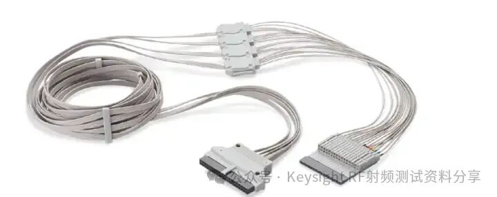
The operating temperature range of the MSO cable is 0°C to 55°C, and its non-operating (storage) temperature range is -40°C to 70°C.
3. Use the probe clip to connect the ground wire to each group of channels (each group). Using the ground wire can improve the fidelity of the signal transmitted to the oscilloscope, ensuring accurate measurements.
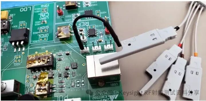
4. Connect the clip to one of the probe wires (the other probe wires are omitted in the figure for clarity).
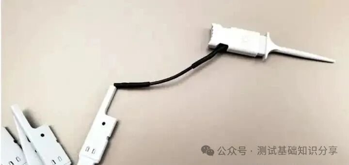
5. Connect the clip to a node in the circuit to be tested.
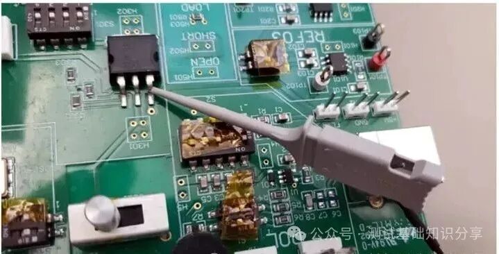
6. For high-speed signal testing, connect the ground wire to the probe wire, connect the clip to the ground wire, and connect the clip to the device under test to ground it.
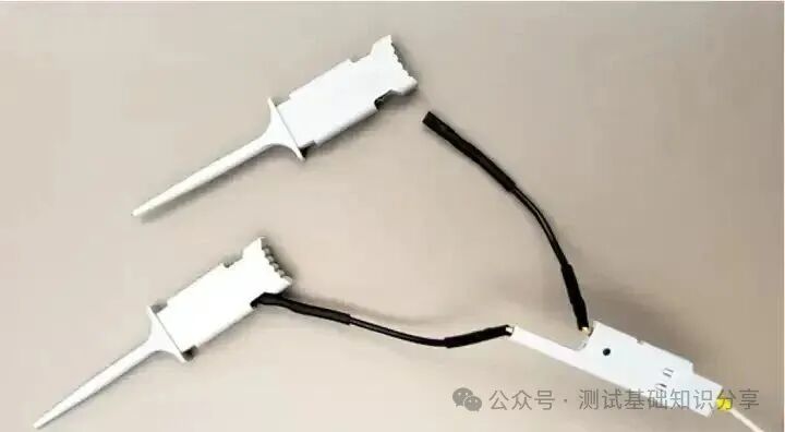
7. Repeat the above steps until all relevant points are connected.
Misunderstandings about Oscilloscope Probe Connections: Just Establish a Stable Connection to Start Measuring
When people see the numerous connection accessories included with oscilloscope probes, they may misunderstand that simply connecting them to the probe is sufficient to achieve measurement goals. These accessories are designed to provide convenience for users, allowing them to perform qualitative measurements quickly and easily, such as checking whether the power is on or if the clock is switching.
Quantitative measurements include rise time, period, overshoot, etc. When performing quantitative measurements, it is best to remove the accessories and use the shortest connections possible. Longer accessories will add inductance to the signal path of the probe, significantly reducing its bandwidth while increasing the probe load on the circuit under test.
Reference:
What is an Oscilloscope Probe? Definition and Classification of Oscilloscope Probes
Essentially, an oscilloscope probe establishes a physical and electronic connection between the test point or signal source and the oscilloscope, converting all the signals you need to measure into voltage signals that the oscilloscope can accept.
-
For example, converting temperature into voltage through a temperature sensor to send to the oscilloscope is a temperature probe;
-
Converting current into voltage through a Hall device to send to the oscilloscope is a current probe;
-
Converting very high voltage into low voltage to send to the oscilloscope is a high-voltage probe;
-
Amplifying very weak voltage signals to send to the oscilloscope is a small signal probe.
Based on these application scenarios, oscilloscope probes can be classified into: voltage probes, logic probes, current probes, temperature probes, optoelectronic conversion probes, etc.
According to the method of implementation, each type of probe can be further subdivided into more different types. For example, voltage probes can be passive probes and active probes, with active probes further divided into single-ended probes and differential probes; current probes can be Hall effect probes, Rogowski probes, and resistive probes, etc.
When purchasing probes, it is essential to pay close attention for the following reasons:
1. For many users, the cost of purchasing probes is not lower than that of oscilloscopes, and probes are more prone to damage than oscilloscopes.
2. Many active probes are not compatible with oscilloscopes from different brands; choosing probes with good compatibility can better protect assets.
3. In oscilloscope measurements, the issues brought by probes far exceed those of the oscilloscope itself, such as probe bandwidth, loading effects, attenuation ratios, dynamic range, offset capabilities, cable bandwidth and length, placement, etc., all of which can affect test results.
Classification of Oscilloscope Voltage Probes
Passive probes, active probes, and some probes for special applications.
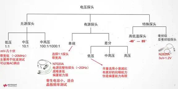
Passive Probes
They can be used without an internal power supply, as they only contain passive components as the name suggests. These probes can adequately cover signals with bandwidths below 600 MHz. They are robust, usually inexpensive, and user-friendly, accurate, and versatile.
Active Probes
Signals with bandwidths exceeding 600 MHz require active probes. Since they contain active components, they require power. They are sometimes powered through a cable with a USB connector or from the oscilloscope’s host itself. These active probes can adjust or amplify signals and cover a broader signal bandwidth, which is why they are often used in high-performance devices and circuits. Therefore, active probes are usually more expensive than passive probes. They are also often more sensitive to damage and heavier. However, these probes do allow testing signals at relatively high frequencies while minimizing capacitive and resistive loading.
Oscilloscope Current Probes
Using your oscilloscope, current probes can measure the current in a circuit. They are typically large and only cover a limited bandwidth of up to 100 MHz.
Classification of Current Probes
Oscilloscope current probes enable the oscilloscope to measure current, extending its use beyond voltage measurements. Essentially, current probes sense the flow of current in some way and convert it into a voltage that can be viewed and measured on the oscilloscope.
The most commonly used current probes today are AC/DC probes that combine current transformers and Hall effect sensors. There are various types of current probes available on the market, and you should understand the principles and pros and cons of each type before reasonably selecting based on your application.
According to different current detection technologies, oscilloscope current probes are generally divided into the following three categories:
1. Resistor sampling current probes: Current detection based on Ohm’s law.
2. Clamp-on current probes: AC probes based on current transformers or AC/DC probes based on hybrid Hall devices/current transformers.
3. Rogowski coils: Convenient probes for measuring large AC currents.
Do not reproduce without permission.