Introduction to the IEC 61850 Protocol Standard
The full name of the IEC 61850 series of standards is Communication Networks and Systems in Substations. It specifies the communication behavior between Intelligent Electronic Devices (IEDs) within substations and the related system requirements.
The IEC 61850 series of standards has been developed by the International Electrotechnical Commission’s Technical Committee 57 (IEC TC57) since 1995. Currently, all 14 parts of IEC 61850 have been approved as international standards. The standardization committee in our country has been synchronously tracking and translating the 61850 series standards, and the standard name adopted domestically is DL/T 860.
IEC 61850 may seem like a new protocol. In fact, it is not. More precisely, it is a new approach to substation automation, a new method that impacts engineering, maintenance, operation, and organization in the power industry. It employs object-oriented modeling techniques and a scalable architecture for future communications to achieve the goal of “one world, one technology, one standard.”
The IEC 61850 standard was originally designed and developed for Substation Automation Systems (SAS), but its core value—unified, object-oriented modeling methods and powerful communication services—has long since transcended the walls of substations, extending to all aspects of power systems and even other industrial fields. It enables interoperability and seamless data exchange between devices from different manufacturers.
Why adopt the IEC 61850 protocol?
Currently, the requirements for substation automation in power systems are becoming increasingly high. We see that substations have evolved from being manned to being staffed with fewer personnel, and now to being unmanned in centralized control modes, with a large amount of protection and measurement/control information collected and sent through automated systems.
With the adoption and promotion of new working methods such as condition-based maintenance and procedural operations, in addition to the traditional incoming quantities of current, voltage, and switch positions, as well as a small number of outgoing switch control signals, the self-diagnostic information of devices and more operational functions need to be realized through the substation automation system. Given the chaotic protocols of the IEC 60870-5 era, direct communication between devices from different manufacturers is almost impossible, which forces us to seek a better substation communication protocol to replace it.
At the same time, to standardize the communication systems in remote control systems, IEC formulated the IEC 60870 series of standards (remote control devices and systems) from 1990 to 2002: the 101 and 104 protocols for communication between substations and control centers, and the 103 protocol for communication in protection and monitoring systems. Due to the lack of standards, consistent testing is impossible, and even if manufacturers provide protocols, they cannot guarantee consistency with the protocols; everything must be seen on-site or coordinated in advance in the laboratory. Manufacturers have differences in technical levels, experience, understanding, etc., leading to increasingly prominent interoperability issues and rising engineering costs, which have become a significant obstacle to the development of the substation automation industry. (This is somewhat similar to the OPC DA/UA protocol we discussed earlier, which is also aimed at communication interoperability between different manufacturers’ software and hardware.)
Digital substations based on the IEC 61850 protocol framework have the following four characteristics compared to traditional integrated automation stations:
1. Definition of the information hierarchical structure of substations
The IEC 61850 standard draft for communication networks and systems in substations proposes the concept of information hierarchy within substations, dividing the communication system into three levels: the substation level, the bay level, and the process level, and defining the communication interfaces between these levels.
The network between the substation level and the bay level uses abstract communication service interfaces mapped to Manufacturing Message Specification (MMS), Transmission Control Protocol/Internet Protocol (TCP/IP) Ethernet, or fiber optic networks.
The network between the bay level and the process level uses one-to-many unidirectional transmission over Ethernet. All IEDs (Intelligent Electronic Devices, such as measurement and control units, protection devices, smart terminals, etc.) within the substation use a unified protocol (GOOSE, GSSE, SV, etc.) for information exchange over the network.
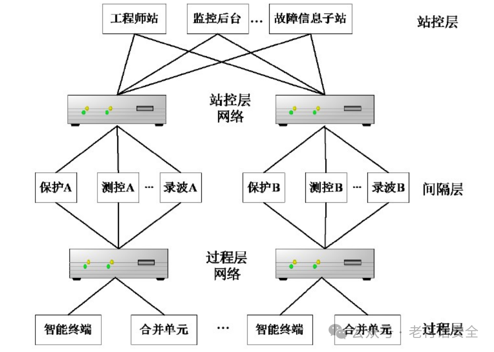
The topology of digital substations compared to traditional integrated automation stations:
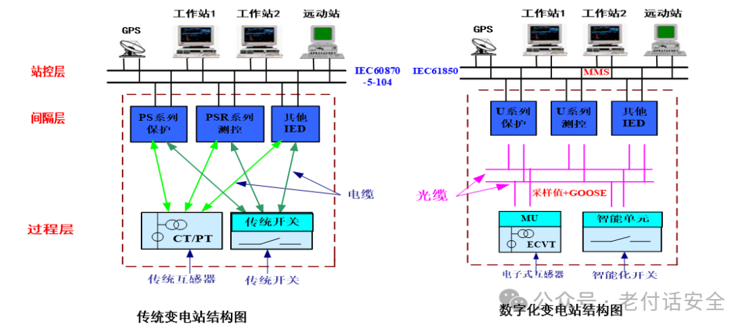
From the hierarchical structure of substations, digital substations consist of the station control layer, bay layer, and process layer.
Station control layer devices: monitoring hosts, engineer stations, etc.
Bay layer devices: protection devices, measurement and control devices, etc.
Process layer devices: optical CT/PT, merging units, smart switches, etc.
From the perspective of the devices used, constructing a complete digital substation requires the following three parts:
1) Intelligent primary equipment
Primary equipment from signal relays to control circuits is designed using microprocessors (smart switches) and optoelectronic technology (passive optical CT). At the same time, the network for digital signal transmission replaces traditional cable connections. In other words, conventional relays and their logic circuits, as well as conventional strong electric analog signals and control cables in the substation’s secondary circuit, are replaced by optoelectronic digital and optical/electrical networks.
2) Networked secondary equipment
Conventional secondary equipment within substations requires establishing corresponding cable or network connections between various functional devices to achieve functions such as relay protection, anti-misoperation, measurement control, fault recording, voltage reactive power control, and synchronous operation. However, when the design of secondary equipment fully complies with the IEC 61850 protocol, all connections between IEDs (Intelligent Electronic Devices) use high-speed network communication, replacing the cable connections between devices in traditional substations. The difference between network links and cable circuits lies not only in the transmission medium and form but also in that the connections between devices in the cable circuit mode are point-to-point cable connections, while in the digital substation, there is no direct physical connection between IEDs; instead, data is unifiedly collected and sent through switches. That is, the data sent by each IED is transmitted by the switch it is connected to across the entire network for sharing, while also receiving data shared by other IEDs on the network through the switch it is connected to. Thus, all secondary cables can actually be eliminated, and many conventional functional devices become logical functional modules.
3) Automated monitoring and management systems. After the substation is fully digitized, we can further incorporate intelligent analysis software into the monitoring system, providing a technical basis for the transition from “periodic maintenance” to “condition-based maintenance.”
At the same time, practical technologies such as “procedural operations” also have better promotion space in digital substations.
2. Adoption of object-oriented data modeling techniques
Compared to the awkward situation of over a hundred versions of the IEC 60870-5-103 protocol used in traditional integrated automation stations, IEC 61850 introduces the concept of “object-oriented modeling.” In the protocol, each IED is treated as a server, hierarchically subdivided into logical devices, logical nodes, data objects, and the data attributes of each object.
Each server contains one or more logical devices. Logical devices contain logical nodes, and logical nodes contain data objects. Data objects are named instances of common data classes composed of data attributes. From a communication perspective, IEDs also play the role of clients. Any client can access data objects through the Abstract Communication Service Interface (ACSI) to communicate with the server.
3. Self-describing data
The standard defines the naming rules for establishing object names using device names, logical node names, instance numbers, and data class names; it employs an object-oriented approach to define communication services between objects.
Object-oriented self-describing data allows the data source to self-describe the data itself, and the data transmitted to the receiving end carries self-explanatory information, eliminating the need for engineering physical quantity correspondence, scale conversion, and other tasks. Since the data itself carries explanations, it can be transmitted without being restricted by predefined limits, simplifying data management and maintenance tasks.
4. Network independence
The IEC 61850 standard summarizes the communication services necessary for information transmission within substations and designs an Abstract Communication Service Interface (ACSI) that is independent of the network and application layer protocols used.
In IEC 61850-7-2, a model of the communication services that standard-compliant servers must provide is established, including server models, logical device models, logical node models, data models, and data set models. Clients access these services through ACSI, which is mapped to specific protocols such as Manufacturing Message Specification (MMS) through the Specific Communication Service Mapping (SCSM). The IEC 61850 standard uses ACSI and SCSM technology to resolve the contradiction between the stability of the standard and the future development of network technologies, meaning that when network technologies evolve, only SCSM needs to be modified without changing ACSI.
IEC 61850 Architecture
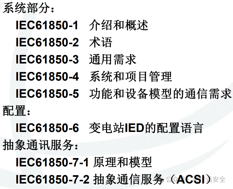
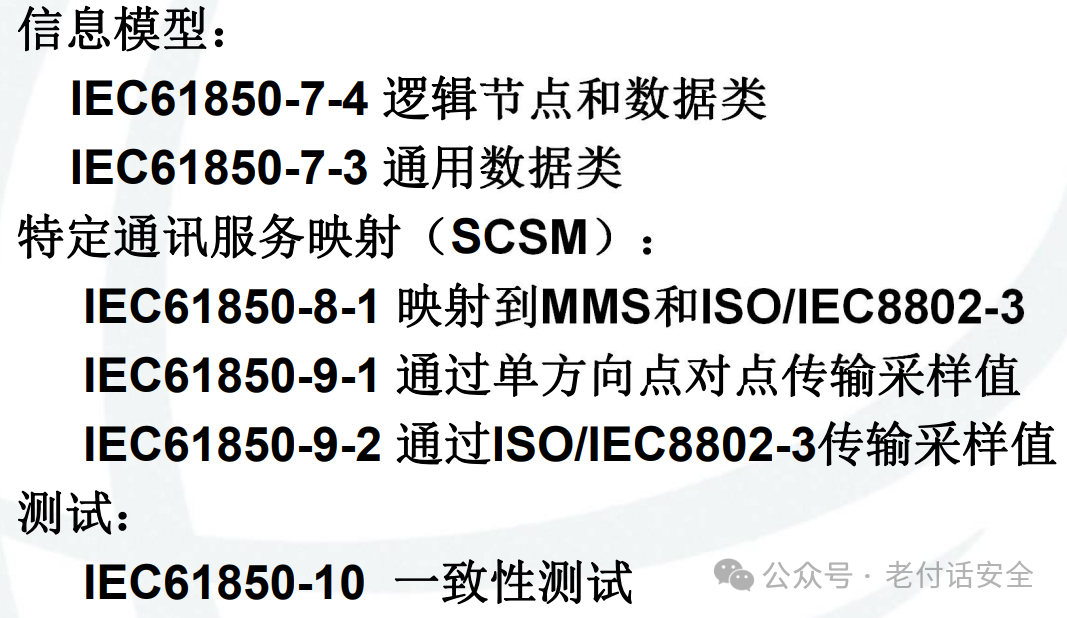
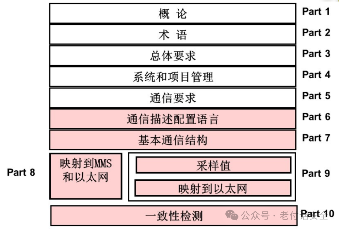
From IEC 61850-8-1 and 9-2, it can be seen that 61850 is like a standard API interface, mapping specific communication services to corresponding protocols such as MMS. This mapping is done through the IEC 61850 service ACSI (equivalent to API).
From the perspective of service usage, a complete digital substation is supported by the following three service components:
1. MMS
MMS: Manufacturing Message Specification (ISO 9506). This standard originated from the message manufacturing specifications established by General Motors in the 1980s. In digital substations, MMS technology is mainly used for the transmission of automated network messages.
2. GOOSE
GOOSE: Generic Object Oriented Substation Events. This service is mainly applied to communication transmission between process layer and bay layer devices in digital substations, essentially replacing the functions of control and signal cables between these devices.
3. SV
SV: Sampled Value. This service is primarily used for the unidirectional transmission of current and voltage sampled values between bay layer devices and process layer.
IEC 61850 Data Exchange Model
The IEC 61850 data exchange model consists of three core parts:
1. Information Model – Standardized Definition of Data
This is the cornerstone of IEC 61850. It adopts an object-oriented approach, abstracting physical devices within substations (such as circuit breakers and voltage transformers) and logical functions (such as protection and measurement) into a unified, computer-understandable object model.
The core hierarchical structure is as follows:
-
Server: Represents a device (such as an IED) that provides data access capabilities externally. An IED can contain one or more servers.
-
Logical Device (LD): A functional unit within the server, typically corresponding to a specific functional area, such as “protection,” “measurement,” or “control.”
-
Logical Node (LN): This is the core of the model. It represents a specific function and serves as a container for data and functions.
-
For example:
<span>XCBR</span>represents a circuit breaker,<span>MMXU</span>represents a measurement unit, and<span>PTOC</span>represents overcurrent protection. -
Each LN has a series of standardized data.
-
Data: Attributes of the LN that describe the status, measurement values, configuration, and other information of that function.
-
For example:
<span>XCBR1.Pos</span>indicates the position of circuit breaker 1 (open/closed), and<span>MMXU1.PhV</span>indicates the phase voltage of measurement unit 1. -
Data consists of more basic data attributes.
-
Data Attributes: Specific values, quality, timestamps, etc. of the data.
-
For example:
<span>XCBR1.Pos.stVal</span>(current value),<span>XCBR1.Pos.q</span>(quality), and<span>XCBR1.Pos.t</span>(timestamp).
Example: In an actual circuit breaker IED, its information model may look like this:
-
Server: IED-001
-
Logical Device: LD0 (system function), CTRL (control function)
-
Logical Node: Under the CTRL logical device, there is a
<span>XCBR1</span>logical node representing circuit breaker 1. -
Data:
<span>XCBR1</span>contains<span>Pos</span>(position),<span>OpCnt</span>(operation count), and<span>BlkOpn</span>(lockout) among other data. -
Data Attributes:
<span>Pos</span>data includes<span>stVal</span>(value=<span>on</span>),<span>q</span>(quality=<span>good</span>), and<span>t</span>(timestamp=<span>2023-10-27 10:00:00.123</span>).
This layered, object-oriented model allows all devices to describe themselves using a unified language, providing a solid foundation for data exchange.
2. Service Model – Methods of Data Exchange
IEC 61850 defines a series of abstract communication service interfaces that specify how clients interact with servers. These services are referred to in the standard as ACSI.
The core services include:
-
Reporting: This is the most important active upload mechanism. Clients can subscribe to data from the server, and when data changes, quality changes, or time-triggered events occur, the server actively sends reports to the client. This replaces the traditional RTU polling, greatly improving real-time performance and efficiency.
-
Key Concepts: Buffered Reporting Control Block (BRCB) and Unbuffered Reporting Control Block (URCB).
-
Logging: Used for storing and retrieving historical data. The server can log data changes with timestamps to a local log, and clients can query these records by time range.
-
Control: Provides operational control over devices, such as opening and closing circuit breakers. Supports enhanced security modes like “select-execute-cancel.”
-
Setting Group: Allows devices to store multiple sets of protection settings and switch between them online.
-
File Transfer: Used for transferring configuration files, fault recording files, and other large data.
-
Sampled Value Transfer: Used for transmitting real-time sampled values from transformers, such as merging units sending current and voltage sampled values to protection and measurement devices. This is typically multicast.
-
Get/Set Services: Classic services for clients to actively read and write server data.
3. Mapping Mechanism – Implementation on Specific Networks
ACSI is abstract and must be mapped to specific, runnable network protocol stacks. IEC 61850-8-1 and IEC 61850-9-2 define this mapping.
-
Manufacturing Message Specification (MMS): This is the core mapping protocol for IEC 61850 client/server communication (such as reporting, control, read/write, file services). MMS itself is a mature international standard that perfectly supports the complex object-oriented data model of IEC 61850.
-
Generic Object Oriented Substation Events (GOOSE): This is a high-speed, reliable, multicast communication mechanism. It directly maps the data model to Ethernet data frames without going through the TCP/IP stack, achieving microsecond-level transmission speeds. It is mainly used for tripping signals, interlocking information, and other scenarios with high real-time requirements.
-
Sampled Values (SV): Similar to GOOSE, this is also a multicast protocol directly mapped to Ethernet data frames, specifically for transmitting real-time sampled value data streams.
Summary Table of Mapping Relationships:
| ACSI Service/Mechanism | Main Communication Protocol Mapping | Application Scenarios |
|---|---|---|
| Reporting, Control, Read/Write, File | MMS (based on TCP/IP) | Data exchange between the station control layer and bay layer, such as between SCADA systems and IEDs |
| Fast Event/Status Transmission | GOOSE (directly mapped to Ethernet) | Between bay layer and process layer, such as protection tripping, switch position interlocking |
| Real-time Sampled Value Transmission | SV (directly mapped to Ethernet) | Process layer, such as merging units sending current and voltage samples to protection and measurement devices |
Example of Actual Data Exchange Process
Scenario: The position of the circuit breaker changes, and the SCADA system needs to update the display.
-
Event Occurs: The circuit breaker
<span>XCBR1</span>changes from “closed” to “open,” and its<span>Pos.stVal</span>value changes. -
Trigger Report: The
<span>XCBR1.Pos</span>data in the IED is configured with reporting functionality (BRCB), and the value change meets the trigger conditions. -
Organize Message: The IED (server) organizes the new value, quality, timestamp, and other information of
<span>XCBR1.Pos</span>into an MMS report message according to MMS mapping rules. -
Network Transmission: The MMS message is sent through the station control layer network (TCP/IP) to the SCADA client that subscribed to the report.
-
Client Processing: The SCADA system receives the report, parses out
<span>XCBR1.Pos.stVal = off</span>, and immediately updates the database and the graphical status of the corresponding circuit breaker in the human-machine interface.
If it is a protection tripping scenario, GOOSE may be used: the protection device detects a fault, immediately organizes a GOOSE message (containing the “tripping” signal), and directly sends it via multicast to the smart terminal, which executes the tripping operation upon receipt. The entire process is completed within a few milliseconds.
The correspondence of GOOSE with the OSI model:
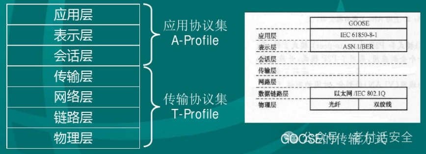
Image source: Internet
From the diagram, it can be seen that the GOOSE message bypasses the network layer, transport layer, and session layer, directly reaching the presentation layer, reducing network overhead and increasing transmission speed. MMS, on the other hand, is a protocol based on TCP/IP, requiring processing through all layers of the OSI model. Thus, MMS is a general, complete application layer protocol that IEC 61850 utilizes. GOOSE is a special application data transmission mechanism defined by the IEC 61850 standard that directly maps to the link layer. It is not a general protocol in itself, but its data construction part belongs to application layer functionality.
MMS: A feature-rich application layer protocol that defines complex encoding rules (ASN.1 BER), session management, variable read/write services, etc. It requires a complete TCP/IP protocol stack support from the lower layers.
GOOSE: It does not have its own independent, complex protocol rules. Its core is a set of predefined data structures and transmission behaviors (such as multicast, retransmission mechanisms). It is more like a standardized “envelope” or “message template” defined at the application layer.GOOSE is a transmission carrier of the application semantics of IEC 61850. It carries application layer data, thus belonging to the “application domain.”
MMS Protocol Stack (through all 7 layers of OSI)
| OSI Layer | Specific Implementation |
|---|---|
| Application Layer | IEC 61850 ACSI Services (such as reporting, control) + MMS Protocol (Manufacturing Message Specification) |
| Presentation Layer | ASN.1 BER (responsible for encoding complex data structures) |
| Session Layer | Handled by mechanisms such as sockets within the TCP/IP stack |
| Transport Layer | TCP |
| Network Layer | IP |
| Link Layer | Ethernet, etc. |
| Physical Layer | Cables, fiber optics, etc. |
GOOSE Protocol Stack (“bypasses” intermediate layers)
| OSI Layer | Specific Implementation |
|---|---|
| Application Layer | IEC 61850 ACSI Services (fast event transmission) + GOOSE Data Structure |
| Presentation Layer | ASN.1 BER |
| Session Layer | Bypassed (connectionless) |
| Transport Layer | Bypassed (no TCP/UDP) |
| Network Layer | Bypassed (no IP addressing) |
| Link Layer | Ethernet (with priority-tagged VLAN frames) |
| Physical Layer | Cables, fiber optics, etc. |
GOOSE messages, after completing the data assembly at the application layer and the ASN.1 BER encoding, are no longer handed over to the TCP/IP protocol stack but are directly injected into the Ethernet data link layer, encapsulated as an Ethernet frame.
GOOSE messages have their own Ethernet type. They use multicast MAC addresses for addressing instead of IP addresses. This is the reason for their extremely fast speed—they bypass the processing overhead of the network and transport layers.
SV (Sampled Value) Protocol Stack
| OSI Layer | Specific Implementation |
|---|---|
| Application Layer | IEC 61850-9-2 / IEC 61850-9-2LE defined sampled value models and services |
| Presentation Layer | ASN.1 BER (basic encoding rules) |
| Session Layer | Bypassed (connectionless, no session management required) |
| Transport Layer | Bypassed (no TCP/UDP) |
| Network Layer | Bypassed (no IP addressing) |
| Link Layer | Ethernet (supports priority-tagged VLAN frames, compliant with IEEE 802.1Q) |
| Physical Layer | Fiber optics (most commonly used) or cables |
Explanation:
Presentation Layer
-
Identical to GOOSE, using ASN.1 BER to binary encode complex data structures defined at the application layer for transmission over the network.
Session Layer, Transport Layer, Network Layer
-
SV messages have extremely high requirements for real-time and periodicity. The retransmission mechanism of TCP and the unpredictable delays of IP routing are unacceptable. Therefore, SV messages, after completing BER encoding, are directly handed over to the network card driver, bypassing the TCP/IP protocol stack of the operating system.
Link Layer
-
The encoded SV data is encapsulated into an Ethernet frame.
-
Destination MAC Address: A preconfigured multicast MAC address (usually starting with 01-0C-CD-04-xx-xx), which all IEDs needing this sampled value (such as protection and measurement devices) subscribe to.
-
Ethernet Type: Set to 0x88BA, which is a dedicated identifier assigned by IEEE for SV messages.
-
VLAN Tag: VLAN and priority tags are typically used to assign high transmission priority to SV messages, ensuring they are not delayed during network congestion.
Comparison of MMS, GOOSE, and SV:
| Feature | MMS | GOOSE | SV |
|---|---|---|---|
| Mapping Protocol | Based on TCP/IP and MMS protocol | ||
| Communication Mode | Client/Server | ||
| Communication Role | Station control layer (client) ↔ Bay layer (server) | ||
| Main Use | Monitoring, control, event reporting, file transfer | ||
| Real-time Performance | Slower (ms ~ 100ms level) | ||
| Data Volume | Variable, relatively small | ||
| Reliability Mechanism | TCP retransmission, acknowledgment |
Major Application Areas of IEC 61850 Beyond Substations
| Application Area | Specific Application Scenarios | How to Use/Extend |
|---|---|---|
| Hydropower | Modeling and monitoring of the entire hydropower station (including turbines, governors, gates, etc.). | Use existing LNs from substations (such as MMXU for measurement) and define hydropower-specific LNs (such as IEC 61850-7-410). |
| Wind Power | Monitoring of wind turbine units (wind turbines, pitch systems, inverters) and the entire wind farm. | Define wind power-specific LNs (such as IEC 61850-7-420) to describe turbine characteristics, wind speed, power output, etc. |
| Photovoltaic Power | Modeling of photovoltaic inverters, combiner boxes, and solar radiation sensors. | Use and extend related LNs for monitoring DC voltage, current, power generation, etc. |
| Distribution Automation | Used for smart distribution switches, fault indicators, and distribution network reconstruction. | GOOSE mechanism shines here, used for rapid fault isolation and restoration of power supply in non-fault areas on distribution network lines (FA function). |
| Electric Vehicle Charging | Realizing communication between charging stations, the grid, and charging operators. | IEC 61850-7-420 includes models for electric vehicle charging infrastructure, defining charging pile status, charging sessions, billing information, etc. |
| Energy Storage Systems (ESS) | Monitoring battery management systems (BMS), power conversion systems (PCS). | Modeling battery packs, charge/discharge status, health, etc., to achieve peak shaving and frequency regulation for the grid. |
| Digital Substations/Digital Twins | Using SCL files to describe the structure of the entire substation or power system as a basis for digital twins. | SCL (System Configuration Language) files provide a complete “blueprint” of the system, useful for system design, debugging, operation, and advanced analysis. |
| Transmission Networks | Used for wide-area measurement systems (WAMS), phasor measurement units (PMU) communication. | Although traditionally using IEEE C37.118, IEC 61850 is also expanding into this field, attempting to unify models. |
| Industrial Automation | Applied in large factories, mines, and ship power systems. | Utilize its strong interoperability to integrate smart devices from different manufacturers, achieving unified energy management and control systems. |
There is a lot of content regarding substation automation. For now, let’s get acquainted with it, and in the future, we will delve into the details of substation network topology. Stay tuned!

End

@Please grant me strength, following and sharing is the greatest support@
+VX: TCMAFNS119 Join the group for discussion