Name
LCD1602 Display Driver for Verilog Quartus EP1C3 Development Board
Software
Quartus
Language
Verilog
Code Functionality
clk_LCD is the 500Hz clock signal required by the LCD_Driver module. The main modules include: Clock_Gen, LCD_Driver, and LCD_Top. The design focuses on the implementation of key functionalities and timing constraints, emphasizing synthesizability and portability, suitable for rapid iteration and verification in a Verilog environment.
Related Images
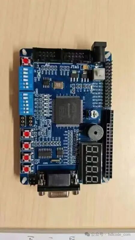
Code Implementation Approach
The overall approach adopts a top-down hierarchical design, first clarifying interfaces and constraints, then refining functional modules. Timing is primarily based on synchronous clocks, with a unified reset strategy. Critical paths are reduced in delay through pipelining or parallel decomposition. The control section uses a finite state machine to organize the process, while the data path buffers and handshakes according to the interface protocol. The verification phase employs simulation and synthesis joint checks, covering boundary conditions and abnormal inputs to ensure stable operation on the FPGA platform. Core modules: Clock_Gen, LCD_Driver, LCD_Top, each responsible for interfaces, control, and computation.
Code Structure
The overall structure adopts a layered and modular design: the top layer is responsible for interface and timing organization, the middle layer is split into control and data channels, and the bottom layer contains specific algorithms and peripheral drivers. A unified clock and reset strategy maintains synchronization, and critical paths introduce pipelining to reduce delays. Modules are coupled and decoupled through clear port protocols, facilitating reuse and expansion. Major submodules include: Clock_Gen, LCD_Driver, LCD_Top, each responsible for interface adaptation, state machine control, buffering, and computation, forming a clear and maintainable architecture.
Partial Code
|
module Clock_Gen(clk_50M,rst,clk_LCD); input clk_50M,rst; // rst is the global reset signal (active high) outputclk_LCD;wire clk_counter; reg [11:0]cnt; // Count the clock for frequency division wire clk_equ; reg [9:0] count; reg clk_BUF; parameter counter = 48; // Frequency division factor /******************************************************************************** ** Module Name: Frequency Divider ** Function Description: Achieves frequency division through a counter. ********************************************************************************/ always@(posedge clk_50M) begin if(!rst) // Low level reset cnt <= 12’d0; else if(clk_equ) cnt <= 12’d0; else cnt <= cnt+1’b1; end assign clk_equ = (cnt==counter); assign clk_counter = clk_equ; always @(posedge clk_counter or negedge rst) begin // Use the counter to generate a 500Hz clock if(!rst) begin clk_BUF <= 1’b0; count <= 10’b0; end else begin if(count == 10’d1000) begin clk_BUF <= ~clk_BUF; count <= 10’b0; end else begin clk_BUF <= clk_BUF; // clk_BUF is the 500Hz clock signal count <= count + 1’b1; end end end assignclk_LCD = clk_BUF; // clk_LCD is the 500Hz clock signal required by the LCD_Driver module endmodule |