
Debugging work is the key task to check whether the PLC control system meets control requirements, and is an objective and comprehensive evaluation of system performance. The entire system must undergo strict debugging of all functions before being put into operation until it meets the requirements and is confirmed by relevant user representatives, supervisors, and designers.
Debugging personnel should be specially trained and be familiar with the composition of the control system, as well as the use and operation of hardware and software.

Input and Output Loop Debugging
01
Analog Input (AI) Loop Debugging
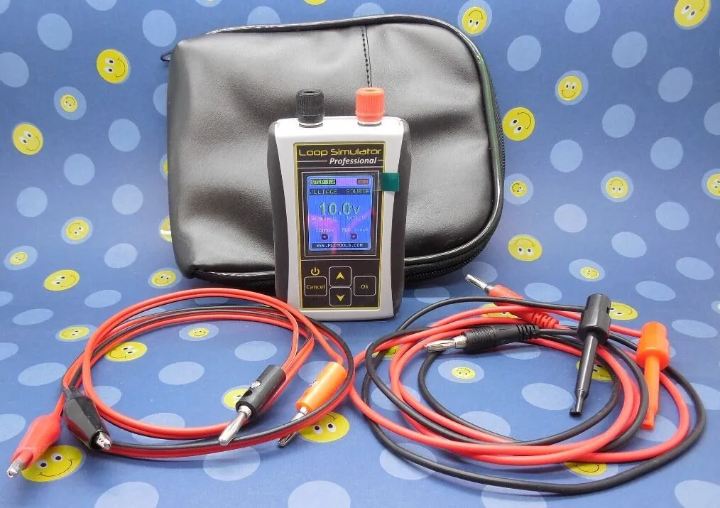
Carefully check the address allocation of the I0 module; check whether the loop power supply method (internal or external) is consistent with the field instruments; use a signal generator to add signals to each channel at the field end, usually checking three points: 0, 50%, or 100%. For AI loops with alarm and interlock values, check the alarm interlock values (such as high alarm, low alarm, interlock points, and accuracy) to confirm the correctness of the relevant alarm and interlock status.
02
Analog Output (AO) Loop Debugging
According to the requirements of loop control, check the actuators (such as valve openings, etc.) using manual output (i.e., directly set in the control system), usually checking three points: 0, 50%, or 100%; at the same time, check whether the output meets the relevant requirements through closed-loop control. For AO loops with alarm and interlock values, check the alarm interlock values (such as high alarm, low alarm, interlock points, and accuracy) to confirm the correctness of the relevant alarm and interlock status.
03
Digital Input (DI) Loop Debugging
Short-circuit or disconnect at the corresponding field end to check the changes of the LED corresponding to the channel address of the digital input module, while checking the changes of the channel’s on and off states.
04
Digital Output (DO) Loop Debugging
Check the output points using the forced functions provided by the PLC system. By forcing, check the changes of the LED corresponding to the channel address of the digital output module, while checking the changes of the channel’s on and off states.
Loop Debugging Precautions
01
For digital input and output loops,
it is important to maintain the principle of state consistency.
The positive logic principle is generally used, which means that when the input and output are powered, it is in the “ON” state, and the data value is “1”; conversely, when the input and output are powered off, it is in the “OFF” state, and the data value is “0”. This makes it easier to understand and maintain.
02
For digital input and output modules with large loads,
they should be isolated from the field through relays.
This means that field contacts should not be directly connected to input and output modules.
03
When using the forced functions provided by the PLC,
be sure to restore the state after testing.
At the same time, do not force too many points at once to avoid damaging the module.

Control Logic Function Debugging
Control logic function debugging must be completed in conjunction with design, process representatives, and project management personnel. Use the processor’s testing functions to set input conditions, and check whether the output state changes according to the processor logic to confirm the control logic function of the system. For all interlock loops, simulate the interlock process conditions, carefully check the correctness of interlock actions, and keep detailed debugging records and confirmations.
Inspection work is the process of acceptance for the design control program software, and it is the most complex, technically demanding, and difficult task in the debugging process. Especially in cases involving patented technologies and specialized software, it is even more critical to check the correctness of the control, ensuring a certain operating margin while guaranteeing the normal operation of process operations, as well as the safety, reliability, and flexibility of the system.

Processor Performance Testing
Processor performance testing must be conducted according to the requirements of the system manual, ensuring that the system has the functions described in the manual and is stable and reliable, including checks on system communication, backup batteries, and other special modules. Systems with redundant configurations must undergo redundancy testing, which involves comprehensive checks of redundant design parts, including power redundancy, processor redundancy, I0 redundancy, and communication redundancy.
01
Power Redundancy
Cut off one power supply, and the system should continue to operate normally without disturbance; the powered-off power supply should return to normal after being powered on.
02
Processor Redundancy
Cut off the main processor power or switch the main processor’s operation switch; the hot standby processor should automatically become the main processor, and the system should run normally without disturbance; the powered-off processor should return to normal and be in standby status after being powered on.
03
I0 Redundancy
Select input and output points that are mutually redundant and correspond to addresses, apply the same input signal to the input module, and connect the output module to a status indication instrument. Turn on and off (or hot swap, if permitted) the redundant input and output modules separately to check if their states can remain unchanged.
04
Communication Redundancy
By cutting off the power of one communication module or disconnecting a network, check whether the system can communicate and operate normally; after resetting, the status of the corresponding module should automatically return to normal.
05
Redundancy Testing
Redundancy checks must be performed on all modules with redundant designs according to design requirements. Additionally, checks on system functions include system self-checks, file searches, file compilations and downloads, maintenance information, backups, and other functions. For more complex PLC systems, the system function checks also include logic diagram configurations, loop configurations, and special I0 functions.
Recommended For You


“Introduction to Siemens S7-200 SMART from Scratch”, published by Hefei University of Technology;
Original price 128 yuan, fan exclusive benefit only 10 yuan, free shipping, limited to the first 50!


10 yuan includes: 275 pages of full-color book + 22 video courses + programming software + simulation software + 100GB learning materials + three days of paid community live courses (teachers available for Q&A at any time)
Limited benefits, what are you waiting for? Hurry up and buy! 👇

Disclaimer:This article is reprinted from the internet, and the copyright belongs to the original author. If there are any copyright issues, please contact us in time to delete it. Thank you!
Complete question bank for the 2022 Junior Electrician Exam (including answers)
Three essential tools for electricians, just one click on WeChat to use!
【Collection】 The “Path” of a ten-year veteran electrician, the secret to earning over 10,000 a month!
Which of the five major electrical drawing software (CAD, Eplan, CADe_simu…) do you pick?
The latest electrical version CAD drawing software, with a super detailed installation tutorial!
The latest electrical drawing software EPLAN, with a super detailed installation tutorial!
Common issues when beginners use S7-200 SMART programming software (download link included)
Super comprehensive electrical calculation EXCEL sheet, generated automatically! No need to seek help for electrical calculations!
Bluetooth headsets, electrician/PLC introductory books to give away? Come and claim your electrical gift!
Basic skills in PLC programming: Ladder diagrams and control circuits (including 1164 practical cases of Mitsubishi PLC)
Still can’t understand electrical diagrams? Basic electrical diagram recognition and simulation software are available, quickly get started with theory and practice!
12 free electrician video courses, 10GB software/e-books, and 30 days of free electrician live courses are being given away!
