Are there still people confused about RS-485 and Modbus? This article aims to clarify the differences for beginners. Experts can skip ahead, but feel free to share this with your novice friends.
RS-485 is a widely used serial data transmission standard in industrial applications. When implementing RS-485 communication, the Modbus protocol is often used, which leads many to conflate RS-485 with Modbus. This article focuses on the following key points:
-
What is RS-485 communication?
-
Half-duplex communication of RS-485?
-
Modbus communication principles?
-
Modbus message format?
-
Differences between RS-485 and Modbus?
【What is RS-485 Communication】
RS-485 is a protocol similar to RS-232 used for serial data communication. These two protocols use different electrical signals for data transmission.
One reason RS-485 is more widely used in industrial environments than RS-232 is that it can serve multiple devices connected to the same bus. This means that when querying multiple devices, there is no need for multiple interfaces; communication can occur by distinguishing the addresses of different devices on the bus, which can be differentiated through software settings, DIP switches, different resistor voltages, etc.
Due to its advantages over RS-232, we often see RS-485 protocols directly connected to USB, GSM, or Ethernet ports, such as in commonly used serial servers in the industrial Internet sector, which primarily convert RS-485 to Ethernet interfaces.
Devices using RS-485 ports typically adopt the Modbus protocol.
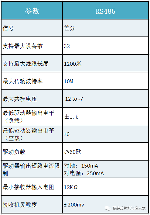
The table below summarizes the characteristics of the RS-485 protocol. RS-485 provides half-duplex transmission over balanced lines, with a transmission distance of up to 1.2 kilometers.
【Half-Duplex Communication of RS-485】
A half-duplex system consists of one or more transmitters and receivers, but only one master can send data at a time. Communication is established by the sender making a request to a specific receiver.
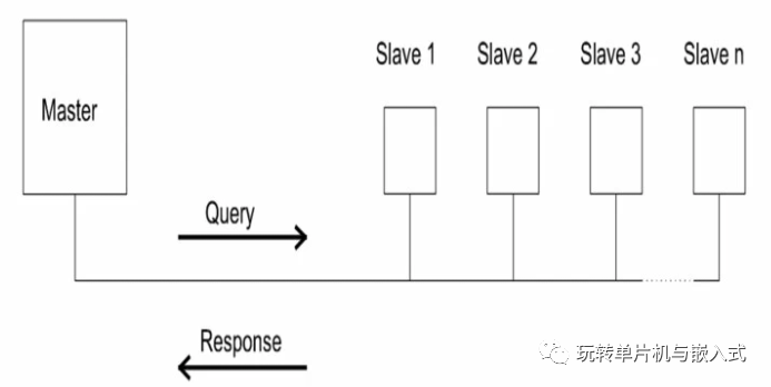
The RS-485 network is built on a master/slave framework. The master acts as the sender, making requests to designated slave receivers. The master listens for responses, and if a response is not received within an appropriate timeframe, it will terminate communication.
【Modbus Communication Principles】
Principles of Modbus messages. In a Modbus RS-485 network, communication begins when the master device sends a query to connected slave devices. The slave devices continuously monitor the network to respond to queries directed specifically at them, either executing an operation or replying to the master.
Queries are initiated only by the master device.
The Modbus protocol allows the master to address messages to specific slave devices or communicate with all slaves simultaneously. This is achieved through a special “broadcast” address. However, some products are designed not to respond to “broadcast” address commands.
Read/write operations are performed using Modbus messages sent via coils. Coils consist of 16-bit words and binary registers. Slaves can only respond to received messages and do not initiate communication with the master.
Each slave device connected to the RS-485 bus is assigned a unique Modbus slave ID. All Modbus communication begins with sending the slave ID to alert the slave to receive the query or inform the master which device provided the response.
Similar to how RS-232 works, both the slave and master devices must ensure that configurations are the same, such as transmission speed (baud rate), parity, and other parameters that need to be synchronized across the entire network.
The Modbus protocol defines the message format used in Modbus communication between the master and slave devices.
Modbus queries consist of the device (or broadcast) address, a function code defining any requested operation, the data returned with the request, and an error check field.
Modbus responses consist of fields verifying that the requested operation was taken, the data sent with the response, and an error check field. If a slave cannot complete the request or an error affects the message reception, the slave will generate an error message as its response.
Modbus communication uses two different serial transmission modes: ASCII and RTU.
Modbus ASCII (American Standard Code for Information Interchange) mode sends each 8-bit message as two ASCII characters. The advantages of ASCII mode include the ability to easily monitor messages on a text console. This mode also allows for a 1-second interval without triggering a timeout.
Modbus RTU (Remote Terminal Unit) mode transmits messages in a different format. Here, the 8-bit message contains two 4-bit hexadecimal characters. Data using this transmission mode must be sent in a continuous stream and, compared to ASCII mode, can achieve better throughput at equivalent baud rates.
Modbus is a protocol. The Modbus protocol defines the message structure used for exchanging data. Modbus can use various types of electrical standards and connect to RS-485. Modbus communication can occur over RS-232, RS-485, RS-422, radio, satellite, or TCP/IP.
Modbus does not define the physical medium of its communication but rather defines the message structure.
RS-485 is an electrical standard.
RS-485 defines the electrical signal levels and wiring that allow data transmission.
In summary: Modbus defines the protocol type, while RS-485 defines the signal levels on the protocol.
Author: Jinan Xingyuan Intelligent Technology Co., Ltd., Source: Playing with Microcontrollers and Embedded Systems.
Disclaimer: This article is reprinted with permission from the “Playing with Microcontrollers and Embedded Systems” public account. The reprint is for learning reference only and does not represent this account’s endorsement of its views, nor does this account assume any infringement liability for its content, text, or images.
🔥 What is the special use of capacitor and resistor in series at the power input?
🔥 [Circuit Notes] Overvoltage (OVP) and Overcurrent (OCP) Protection Circuits in Circuits
🔥 DCDC Inductor Selection and Calculation
🔥 If you don’t draw this circuit, the development board won’t start
🔥 As PCBs get smaller, PCB testing becomes increasingly difficult?
👇 Free Development Board Application 👇