(1) Introduction
RS-485 is a balanced transmission standard for serial communication approved by the Electronic Industries Alliance in the United States in 1983. It only specifies the electrical characteristics of drivers and receivers without defining a protocol; therefore, many higher-level interface standards refer to RS-485 at the physical layer, such as Modbus, Profibus, etc.
(2) Key Features
Differential transmission enhances noise immunity and reduces noise radiation;
Long-distance transmission, up to 1219 meters
Data rates up to 10 Mbps within 10 meters
Multiple drivers and receivers can be connected on the same bus;
Wide common-mode range allows for ground potential differences between drivers and receivers, allowing a maximum common-mode voltage of -7 to 12V
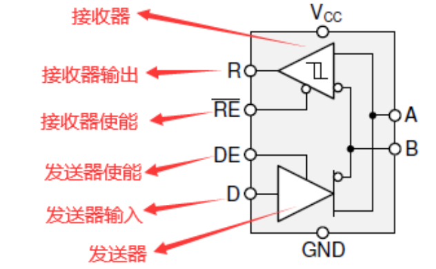
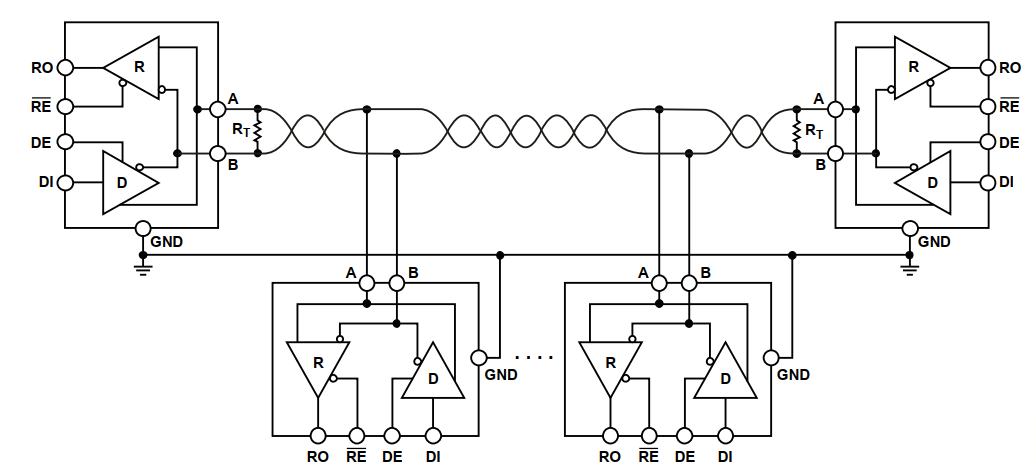
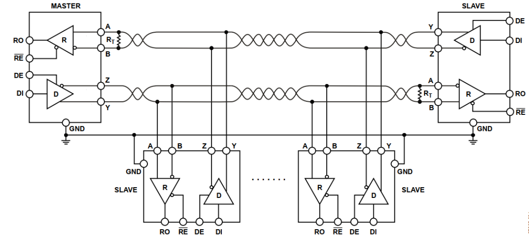
(3) Typical Block Diagram of Transceiver
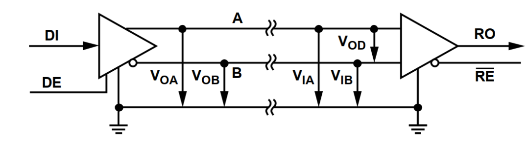
(4) Signal Levels
The differential lines of RS-485 are designated as A and B. If a logic high level (DI=1) is received at the input of the transmitter, the voltage on line A is higher than that on line B (Voa>Vob); if a logic low level (DI=0) is received at the input of the transmitter, the transmitter makes the voltage on line B higher than that on line A (Vob>Voa)
If the voltage on line A is higher than that on line B (Via-Vib>200mV) at the input of the receiver, the output of the receiver is a logic high level (RO=1); if the voltage on line B is higher than that on line A (Vib-Via>200mV), the output of the receiver is a logic low level (RO=0)
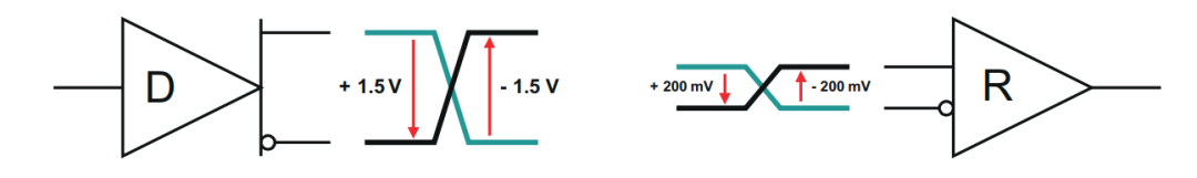
The RS-485 standard specifies that the driver must provide a differential output of no less than 1.5V (under a 54Ω load), and the receiver must be able to detect differential signal inputs as low as 200mV; this ensures sufficient margin for reliable data transmission even in cases of severe degradation of cables and connectors.
(5) Network Topology
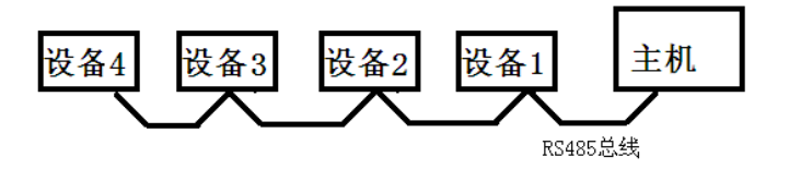
RS-485 is recommended for use in point-to-point networks, linear, and bus-type configurations; star or ring networks are not permitted; as shown in the figure
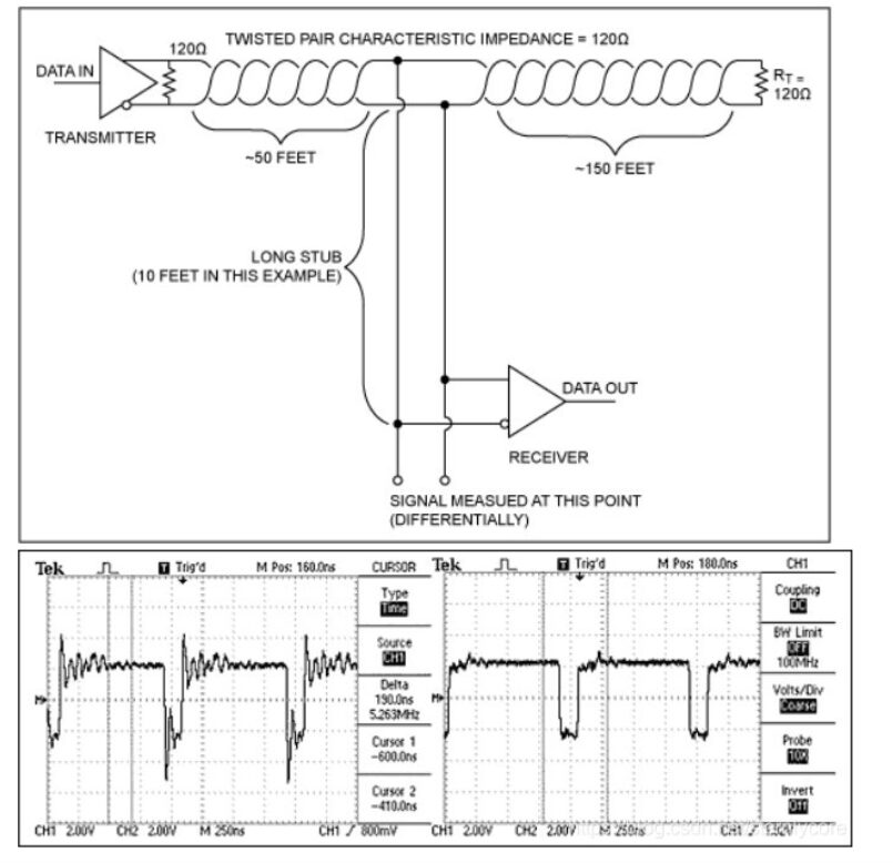
(6) Bus Termination and Branch Lengths
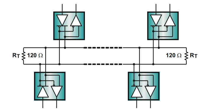
To avoid signal reflections, the data transmission line should always be terminated, and branch lengths should be kept as short as possible; proper termination requires that the termination resistor Rt matches the characteristic impedance Zo of the transmission cable; the RS-485 standard recommends that the cable Zo = 120Ω, so the cable trunk is usually terminated with a 120Ω resistor
The branch length (the distance between the transceiver and the cable trunk) should be less than 1/10 of the driver’s output rise time and is derived from the following formula
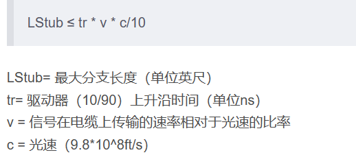
Excessively long branch lengths can cause signal transmission reflections affecting impedance; the following figure compares waveforms of long and short branch lengths: