 Search on WeChat
 Automation Knowledge Base
When I first started working in PLC debugging, I once followed my mentor to the site to troubleshoot a servo motor failure. That day, my mentor pointed to a knob on the driver and asked me, “Do you know which control method this device uses?” I stared at the parameters on the screen for a long time without saying a word—I always felt that the three modes of servo control were abstract and convoluted until I later adjusted devices in different scenarios myself, which helped me truly grasp these concepts.
In fact, the control methods for servo motors are not that mysterious; they can be categorized into three core types: speed control, torque control, and position control. Simply put, the first two rely on analog signals for control, while position control relies on pulse signals. As for which one to choose, it ultimately depends on the on-site requirements—what actions the customer wants to achieve will dictate the method we use.
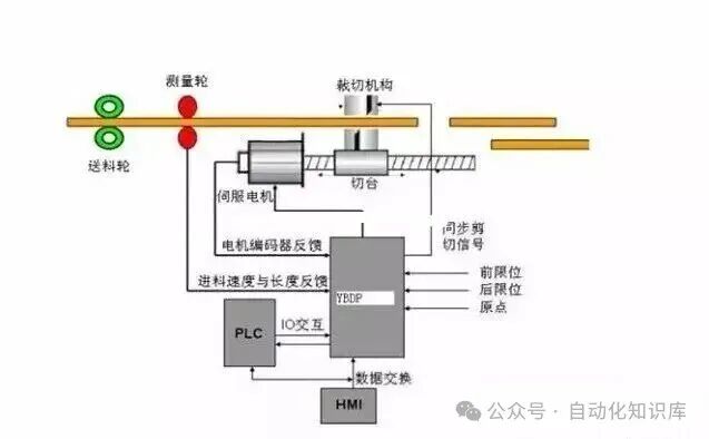
Let’s start with a diagram to help everyone establish an intuitive impression, and then we will break it down one by one:
1. Understand the Core Logic: How to Choose Among the Three Methods?
Many beginners are often intimidated by terms like “torque” and “pulse” when they first encounter them. However, I have summarized a simple judgment method that you can follow:
🔹 Only concerned with torque, regardless of speed and position? Choose torque mode.
For example, in a winding machine in the workshop, it doesn’t matter whether the reel turns fast or slow, as long as the pulling force on the material remains constant. In this scenario, torque mode is the optimal solution, without needing to worry about speed and position accuracy.
🔹 Concerned about position and speed accuracy, but not about force? Choose speed or position mode.
Take a common automatic labeling machine, for instance; the label must be applied at a specified position, and the speed must be stable during application, or else the label may misalign. In scenarios where there are clear requirements for position and speed, torque mode should not be used; speed or position mode is more reliable.
🔹 Is the upper controller powerful enough? Prioritize speed control; if the requirements are not high or the controller is average, choose position control.
I previously debugged a production line using a high-end PLC with fast computation speed, so I decisively used speed control, allowing the PLC to perform closed-loop adjustments while the driver was only responsible for execution, which significantly improved efficiency. However, later I encountered an older device with a controller from over a decade ago that was very slow, so I switched to position control, letting the driver handle the complex calculations, which turned out to be more stable.
2. Key Knowledge Points: Response Speed and Dynamic Performance
After working with servo debugging for a while, you will definitely be asked, “How well does this driver control?” There is actually a very intuitive standard for judgment—response bandwidth, but let’s start with the more fundamental response speed.
⚡ Response speed ranking: Torque mode > Speed mode > Position mode
Why is this the case? Because the computational load is different. Torque mode only needs to control current, which is the simplest computation, so it has the fastest response; position mode has to handle position, speed, and current signals simultaneously, resulting in the largest computational load and naturally the slowest response.
For example, I once worked on a high-speed sorting machine that required the material to stop and switch tracks within 0.1 seconds after reaching the designated position. Initially, I used position mode, but it was always off by 0.02 seconds, causing the material to occasionally misalign; after switching to torque mode, the response speed improved immediately, and the problem was resolved.
🔧 High dynamic performance requirements? Look at the controller’s computational ability.
If the device needs to frequently adjust speed or force during operation, such as when a precision machine tool processes parts and needs to adjust cutting force in real-time based on material changes, this requires high dynamic performance. In this case, which mode to choose depends on whether the controller’s “brain” is fast enough:
-
Slow controller (e.g., ordinary PLC, low-end motion controller): Choose position mode, letting the driver do more work.
-
Fast controller: Choose speed mode, moving the position loop to the controller to improve efficiency.
-
High-end dedicated controller: You can try torque mode, moving the speed loop to the controller for maximum precision (generally only used for complex devices).
3. Hardcore Knowledge: How to Measure Response Bandwidth?
As mentioned earlier, response bandwidth is an intuitive standard for judging the quality of a driver, and some friends may be curious about how to measure it. In fact, it doesn’t require overly complex equipment; I have measured it both in the lab and on-site, and the method is quite simple:
📏 Testing Method: Square Wave Signal + Oscilloscope
Connect a pulse generator to the driver, sending a square wave signal to continuously switch the motor between forward and reverse. Then use an oscilloscope to observe the signal, gradually increasing the frequency. When the peak value displayed on the oscilloscope drops to 70.7% of the maximum value, the motor starts to lose steps, and the frequency at this point is the response bandwidth.
For reference, the current loop can generally achieve over 1000Hz, while the speed loop can only reach several tens of Hertz. I previously measured an imported driver with a current loop bandwidth of 1200Hz, which was indeed stable for high-speed applications; whereas a domestic low-end driver had a current loop of only 800Hz, which struggled during high-speed operation.
4. Detailed Breakdown: Specifics and Applications of the Three Control Methods
Having covered the basic logic, let’s delve deeper into the specific usage of each mode, using examples I’ve encountered to help you remember.
01 Torque Control: The “Precision Controller” of Force
The core of torque control is “controlling force”; it sets the motor output force through external analog signals or address assignments. For example, if 10V corresponds to 5Nm of force, then a 5V signal will result in an output of 2.5Nm.
There is an interesting phenomenon here: if the load is less than 2.5Nm, the motor will rotate forward; if it equals 2.5Nm, the motor will stop; if it exceeds 2.5Nm, the motor will rotate in reverse—I’ve seen this situation on a lifting platform, where if the load exceeds the set force, it will slowly descend, which is the principle behind it.
🔍 Typical Applications: Winding and Unwinding Equipment
The most common example is the winding machine for wires and cables. I previously debugged a winding machine where the wire was wound onto a reel, and as the winding increased, the radius became larger. If the force remained constant, the wire could easily break. In this case, torque control is necessary; as the radius of the reel increases, the output force must be reduced in real-time to ensure the wire is evenly stressed. In this scenario, torque control is absolutely essential.
02 Position Control: The “Precise Navigator” of Position
The core of position control is “controlling position and speed”; it determines speed through the pulse frequency of external inputs and angle through the number of pulses. Some servos can also directly assign values for speed and displacement through communication, making operation more convenient.
The advantage of this mode lies in its dual precision control of position and speed. I previously worked on an automatic screw tightening machine that required screws to be tightened to a specified depth, and the speed had to be stable to avoid stripping. After using position control mode, I set the number of pulses to determine the depth of tightening and the pulse frequency to determine the tightening speed, which perfectly solved the problem.
🔍 Typical Applications: Equipment with High Positioning Requirements
In addition to screw tightening machines, CNC machine tools, printing machinery, and automatic assembly lines commonly use position control. For example, the paper positioning in a printing machine must be accurate to the millimeter level; otherwise, the printed pattern will misalign, making position control the best choice.
03 Speed Control: The “Stable Regulator” of Speed
The core of speed control is “controlling speed”; it can be controlled through analog input or pulse frequency. Some may ask if speed control can also achieve positioning. It can, but it requires the upper controller to perform external PID adjustments and feedback the position signal of the motor or load to the controller.
I previously debugged a belt conveyor line that required a stable conveying speed of 0.5m/s and the ability to fine-tune the speed based on the amount of material. After using speed control mode, I set the reference speed through an analog signal and adjusted the analog signal in real-time based on the material quantity detected by sensors, achieving very stable speed control.
Additionally, here’s a little trick: if you place the position detection on the final load and the motor shaft encoder only measures speed, the positioning accuracy will be higher. I used this method on a robotic arm, reducing transmission errors and improving positioning accuracy from 0.1mm to 0.05mm.
🔍 Typical Applications: Equipment with High Stability Speed Requirements
Belt conveyors, fans, and pumps that require stable speeds commonly use speed control. For instance, factory cooling fans require stable airflow; otherwise, the cooling effect will be uneven, and speed control mode can easily achieve this.
5. Ultimate Logic: What is the “Three Loop Control” of Servo?
At this point, it is essential to clarify the “three loop control” of servo motors, which is the core logic for understanding the three control methods. Regardless of which mode is used, the servo internally performs three closed-loop adjustments, like a three-layer safety net, ensuring control precision.
🔴 Innermost Loop: Current Loop (Torque Loop)
The current loop operates entirely within the driver, using Hall elements to detect output current and performing PID adjustments with the set current to ensure precise output current. It essentially controls the motor torque, which is why torque mode only utilizes the current loop, resulting in the least computational load and the fastest response.
🟢 Middle Loop: Speed Loop
The speed loop uses signals from the motor encoder for feedback and performs PID adjustments with the set speed, with the adjusted output directly serving as the setpoint for the current loop. Therefore, speed mode utilizes both the speed loop and the current loop, resulting in a larger computational load and a slightly slower response.
🔵 Outermost Loop: Position Loop
The position loop can be internal to the driver or external to the controller, using position signals for feedback and performing PID adjustments with the set position, with the output serving as the setpoint for the speed loop. Position mode utilizes all three loops, resulting in the largest computational load and the slowest response.
To put it simply: the current loop is like a chef controlling the heat, the speed loop is like controlling the stirring speed, and the position loop is like controlling the timing of when the dish is ready. The three modes essentially use different combinations of these “loops”; once you understand this logic, you will have fully grasped the core of servo control.
Final Summary
The three control methods for servo motors do not have absolute good or bad; the key is to match the scenario:
-
To control force, choose torque mode (winding, unwinding).
-
To control position and speed accuracy, choose position mode (machine tools, screw tightening machines).
-
To control stable speed, choose speed mode (conveyor lines, fans).
When I first started learning, I often mixed up these modes. Later, I went to the site for debugging with questions, followed my mentor to disassemble drivers, check parameters, and modify programs, and gradually I figured it out. Everyone can also practice more, observe more, and when encountering something unclear, think about it in conjunction with actual equipment; you will definitely be able to master these knowledge points.
If you find this content helpful, feel free to like and save it, and you can also discuss the issues you encounter while debugging servos in the comments section; let’s exchange and improve together.
Previous Recommendations
Do electricians only know how to tighten screws? These 5 commonly used formulas can help you avoid three years of detours.
A hands-on guide to understanding NPN transistors, helping you avoid a significant portion of the learning curve for microcontrollers.
Is your servo motor always “shaking”? Here are 10 troubleshooting points summarized by an experienced technician; you can directly apply them to solve the issue.
5 practical PLC programming cases; mastering them makes you an advanced electrician! Understanding them allows you to negotiate a raise with your boss directly.
Proven effective! A practical guide for S7-1200 PLC and V90 servo communication control that even beginners can understand.
PLC control of stepper drivers is actually that simple! (Includes practical wiring diagrams).
Experienced electricians share their top 12 PLC programming tips; beginners can avoid three years of detours after reading.
PLC engineers’ secret techniques: view code flow directly on HMI, no need to panic when equipment stops!
A comprehensive wiring diagram for electricians! Never fear “looks easy but fails” again.
A comprehensive list of cable codes that 90% of peers have saved!
Share this Save this
 View
View Like thisFollow for moreSo you can find me next time