In industrial control environments, the inconsistency of baud rates among different devices’ serial ports (such as RS485 and RS232) is a common headache. To unify control of these devices by the main control board or PLC, it is essential to ensure consistent baud rates. However, some devices allow manual baud rate settings, while others are fixed and cannot be adjusted.
Based on this pain point, I started developing a bidirectional transparent baud rate converter in 2018, and after repeated testing and improvements, the first generation of the product has been successfully implemented and is now used in dozens of industrial projects. Today, I will explain the core logic of baud rate conversion using the PIC microcontroller, techniques for achieving special baud rates, and the design of anti-interference circuits, making it accessible even for beginners.
1. Core Solution: PIC Microcontroller Selection and Hardware Design
The key to baud rate conversion is “dual UART + stable hardware“, which must meet the common baud rate conversion requirements while also adapting to the anti-interference needs of industrial sites.
1. Microcontroller Selection: Choose the Model Based on Baud Rate Requirements
- Standard Requirements (≤1Mbps): The preferred choice is PIC16F1947, which has two built-in UART interfaces and a maximum main frequency of 32MHz, fully covering common baud rates such as 2400, 9600, and 115200. It offers high cost-performance and is the main choice for industrial scenarios;
- High-Speed Requirements (>1Mbps): For example, to achieve 4.8M and 5Mbps baud rate conversion, it is recommended to select the PIC32MX series, which has a wider frequency adjustment range (supporting 30M, 50M, 75M, and 80M, etc.), meeting the timing requirements for high-speed baud rates.
2. Hardware Circuit: RS232 + RS485 Dual Interface Design (Industrial Grade Stability)
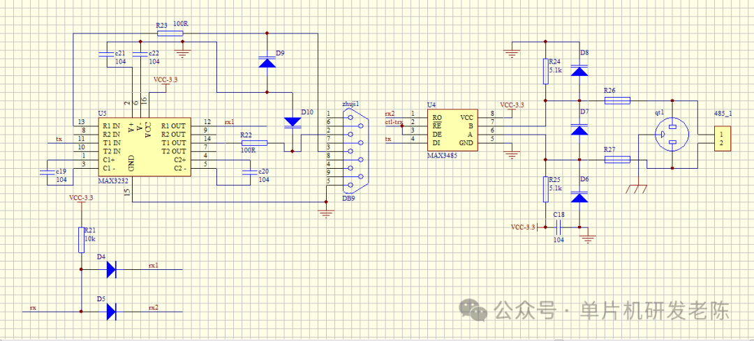
The core of the circuit is “dual interface sharing the CPU RX pin“, while enhancing the anti-interference design. The specific circuit is as follows (key components are labeled):
Key Design Points (Must-See for Beginners):
- Interface Reuse Technique: RS232 and RS485 share the CPU’s RX pin, achieved through a 1N5819 Schottky diode (D4, D5) + 10K pull-up resistor (R21) without occupying additional IO ports, simplifying the hardware structure;
- Core Chip Selection: Use MAX3232 chip for RS232 and MAX3485 chip for RS485, ensuring the power supply matches the microcontroller (3.3V), to avoid communication failures due to level mismatches;
- Current Limiting and Protection: RXD and TXD pins are connected in series with a 100Ω resistor (R23, R27), preventing excessive current from burning out the chip; retain the triple protection for RS485 (gas discharge tube qt1, TVS diode D6, etc.), to cope with surges and electromagnetic interference in industrial environments;
- Component Parameter Reference: Specific resistor and capacitor selections can refer to my previous article “In-Depth Analysis of RS-232, RS-485, and RS-422 Buses and Practical Protection Circuits”.
3. Essential Anti-Interference Circuit: RC Filtering + Grounding Design
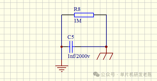
Electromagnetic interference is strong in industrial environments, and adding a simple RC circuit can significantly enhance stability. This is my tested effective “low-cost anti-interference technique“:
Circuit Details:
- Composed of a resistor R8 (1M-10MΩ) and a capacitor C5 (1nF/2000V) in parallel, one end connected to the power supply GND, and the other end connected to the ground;
- The resistor suppresses low-frequency interference, while the capacitor filters high-frequency interference (such as electromagnetic radiation). A capacitor with a voltage rating of 2000V or higher can handle sudden surges, preventing breakdown and damage to the core chip.
2. Core of Baud Rate Conversion: Formula + Practical Cases (Including Special Baud Rates)
The essence of baud rate conversion is “achieving different baud rate transmission and reception adaptation through the microcontroller’s main frequency and register configuration“, with the core formula and practical cases as follows, which can be directly applied.
1. Core Formula: Relationship Between Baud Rate and Main Frequency
The baud rate calculation follows the formula:baud = Fosc / [4×(n+1)]
- Fosc: Microcontroller main frequency (such as 15M, 32M, 76.8M, 80M, etc.);
- n: Baud rate register configuration value;
- For common baud rates (2400, 9600, 115200, etc.), the decimal part of n can be rounded; for special baud rates, it must be ensured that n is an integer, otherwise the main frequency needs to be adjusted.
2. Practical Cases: Common + Special Baud Rate Implementation
(1) Standard Baud Rate Conversion (PIC16F1947 + 15M Crystal)
- Requirement: Convert 187500 baud rate to 115200 baud rate;
- 187500 baud rate calculation: n = (Fosc / (4×baud)) – 1 = (15M / (4×187500)) – 1 = 19 (integer, directly configured);
- 115200 baud rate calculation: n = (15M / (4×115200)) – 1 ≈ 31.55, rounded to 32 (communication is stable in practice, with an error within the industrial allowable range).
(2) Special Baud Rate Implementation (PIC32MX + 76.8M Main Frequency)
- Requirement: Convert 4.8M baud rate (high-speed scenario);
- 4.8M baud rate calculation: n = (76.8M / (4×4.8M)) – 1 = 3 (integer, perfectly adapted);
- Key: The PIC32MX series supports higher main frequencies (76.8M), which is essential for achieving special high baud rates like 4.8M and 3.125M. Using the PIC16F series would not meet the main frequency requirements.
(3) Other Special Baud Rate Configuration References
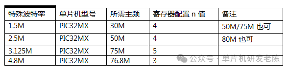
Note: All configurations have been tested in industrial environments, with communication errors ≤1%, meeting the communication standards of RS485/RS232.
3. Industrial-Level Pitfall Avoidance Techniques: Avoid These Mistakes!
- Ignoring the integer requirement for n: Special baud rates (such as 187500 and 4.8M) must ensure that n is an integer; otherwise, packet loss and garbled data may occur. Prioritize adjusting the main frequency (rather than rounding) to meet this requirement;
- Unstable power supply voltage: High-speed baud rates (>1Mbps) have higher power supply requirements. It is recommended to add a 100μF electrolytic capacitor + 0.1μF ceramic capacitor at the power supply end;
- Not adding an RC anti-interference circuit: Even for standard baud rates in industrial environments, not adding an RC filter may lead to communication interruptions due to interference. This low-cost circuit must be included;
- Using ordinary diodes instead of Schottky diodes for interface reuse: Replacing 1N5819 with ordinary diodes will cause signal attenuation and may even lead to unrecognizable signals. It is best to use Schottky diodes (lower forward voltage drop, faster response);
- Improper crystal selection: Special baud rates require high precision for crystals. It is recommended to use high-precision external crystals instead of the microcontroller’s internal RC oscillator (which has low precision and is easily affected by temperature).
What special baud rate requirements have you encountered in industrial settings? Or have you faced issues like packet loss or garbled data during baud rate conversion? Feel free to leave a comment, and I will respond to each one!
More valuable content is coming, let’s progress together in the world of microcontrollers.