The so-called backlight method involves soaking plastic parts in hydrogen peroxide and exposing them to UV light. After a period of time, the yellowed parts can be whitened, restoring them to their original state.
Using a 20W UV lamp to achieve rejuvenation Author: ecoren, Source: Breadboard Community【DIY Activities】Recently, I wanted to refurbish the old yellow casing of my multimeter using the backlight method. I found that a 20W UV lamp on an online store costs over 100, so I thought it would be better to make one myself. Not only would it satisfy my DIY itch, but it would also better meet my actual needs and save money.I first drew a lamp board using an aluminum substrate. I used eighty-one 3528 package LEDs with a wavelength of 395nm. It was configured in a series of 3 and parallel of 27. The 10x10cm aluminum substrate was quite difficult to solder, and I had to use a hot plate to get it done properly.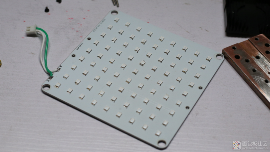 Now that I had the lamp board, I needed to design a driver board. The schematic was quickly drawn up, mainly consisting of two parts: one is a PD spoofing circuit using the ch224k, which tricks the circuit into thinking it’s 12V; the other is an LED constant current driving circuit, where the current is set by R11, and I configured it for a driving current of 2A.
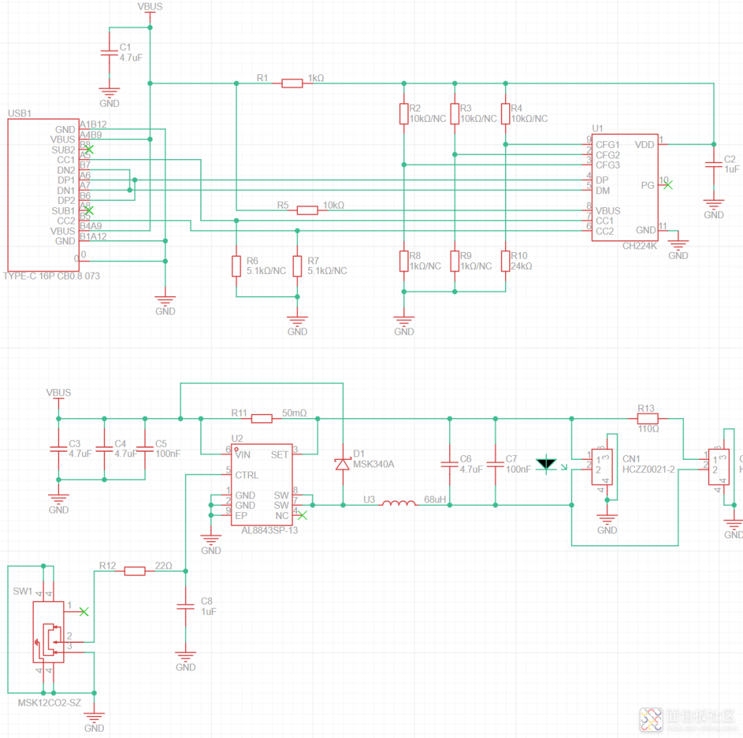 The circuit board is also 10x10cm in size, just like the lamp board. I made a yellow board, which looks quite nice. That 68uH inductor has a kind of stylish vibe.
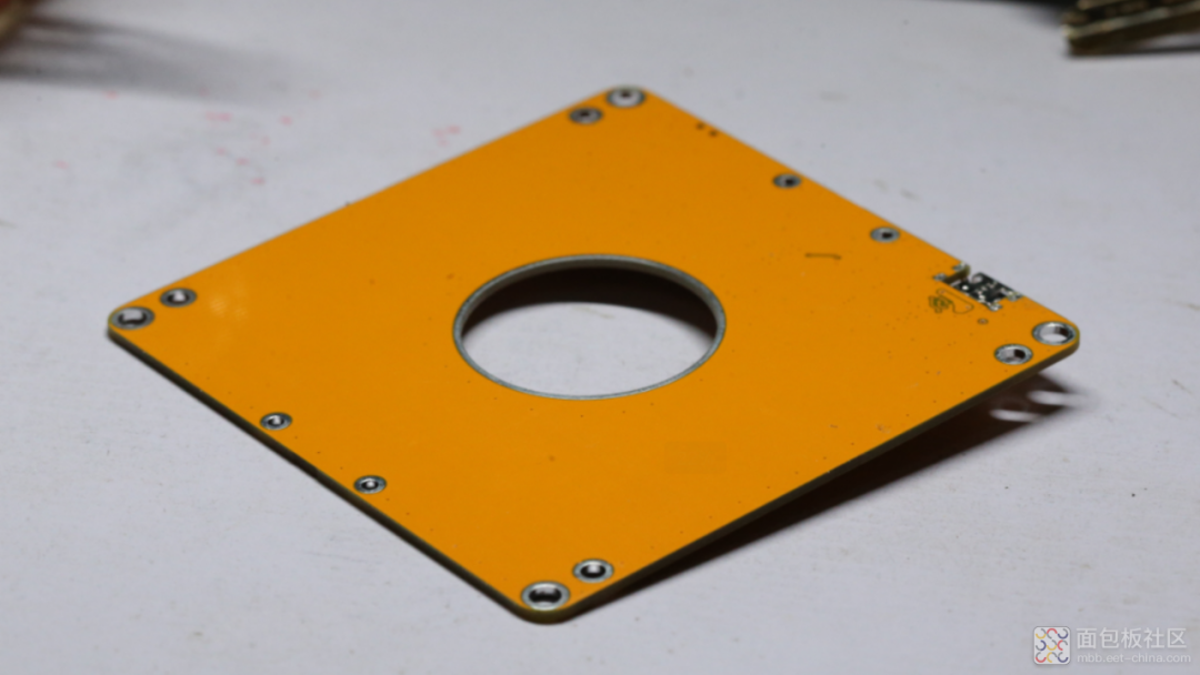 Although the yellow board is a double-layer board, I placed the components on one side only. The large hole in the middle is reserved for a ventilation duct for the cooling fan.
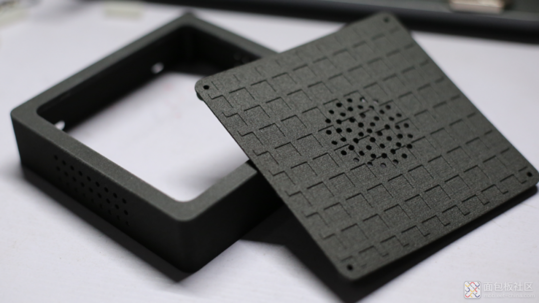
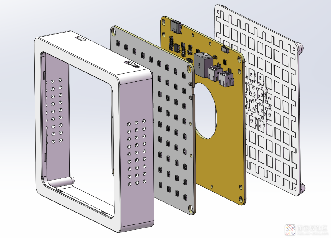 In recent years, DIY has become more sophisticated, so I had to design a case, and I also made an assembly drawing.I found a third-party printing factory to make the shell using nylon material, which does not leak light.
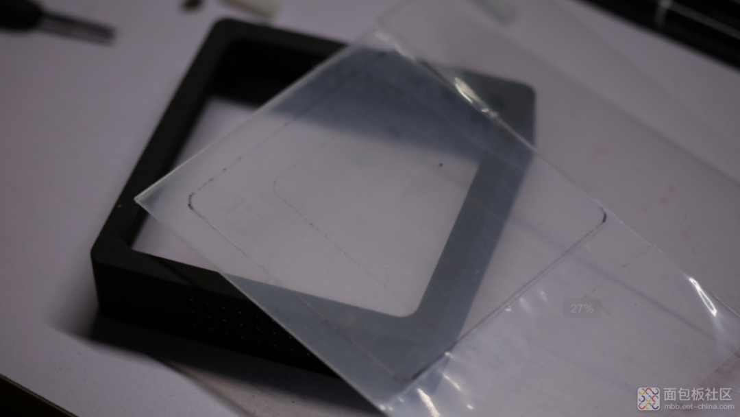
 Then I handmade a light-transmitting panel using acrylic. It was cut manually with a utility knife, using a 1mm thick acrylic sheet.
 It’s also a 20W device, and since I have a fan and copper plate on hand, I decided to create an active cooling system manually.
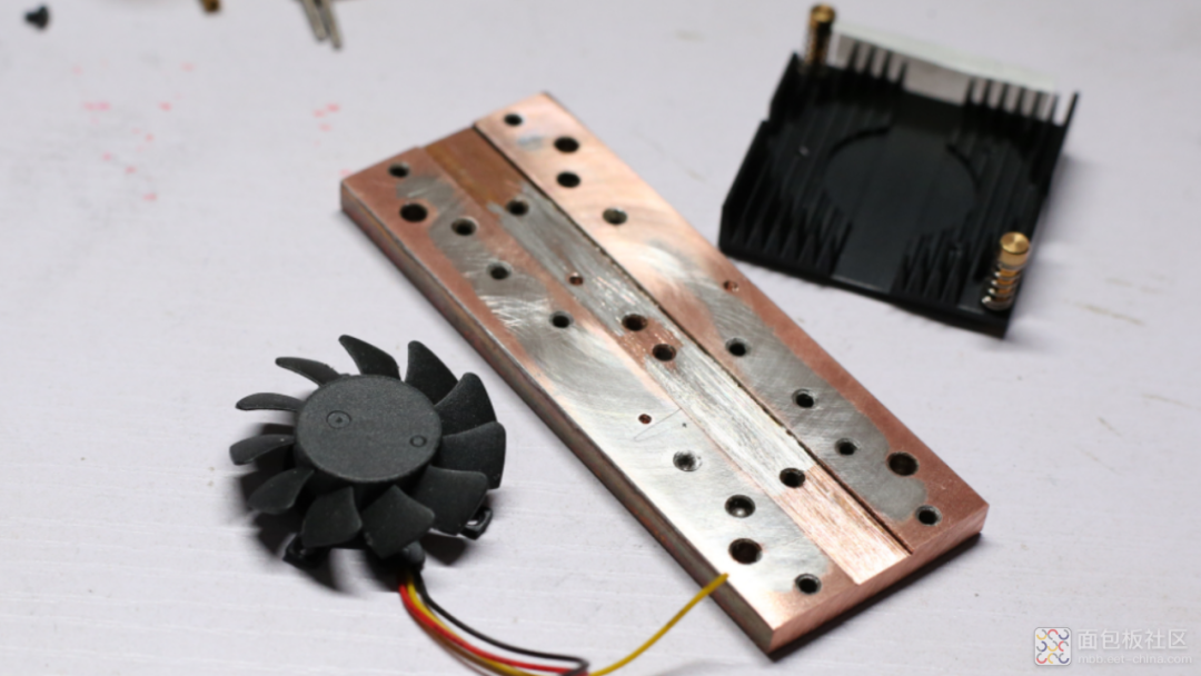 It was installed perfectly onto the LED lamp board. Actually, I had measured their dimensions during the design phase and reserved installation holes for the copper plate and fan, so the assembly went very smoothly.
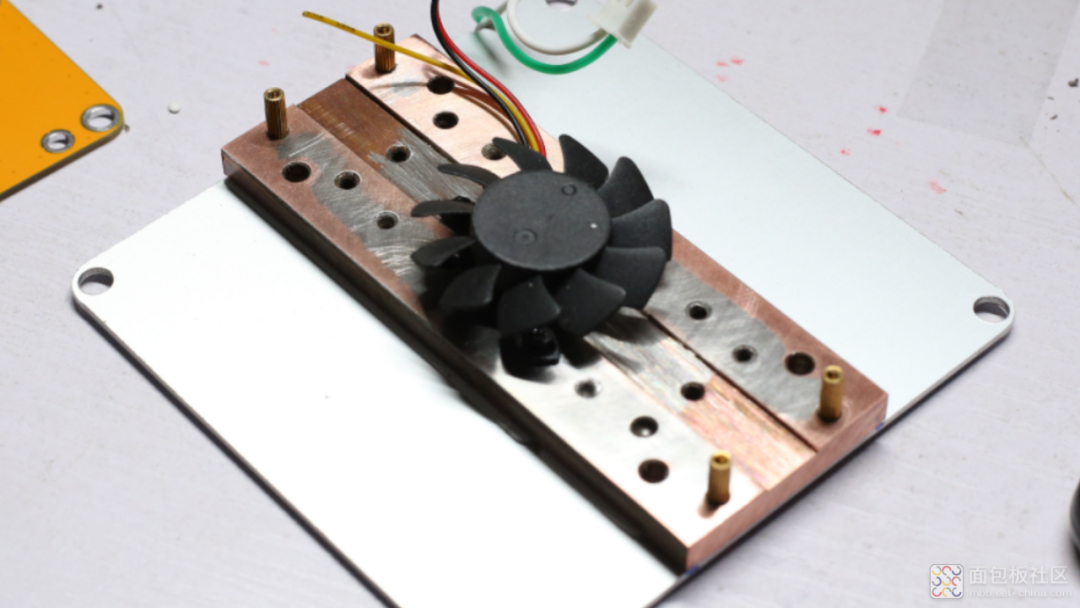 I placed the lamp board and its heat sink into the case. Thanks to the 3D assembly drawing, the installation was very smooth.
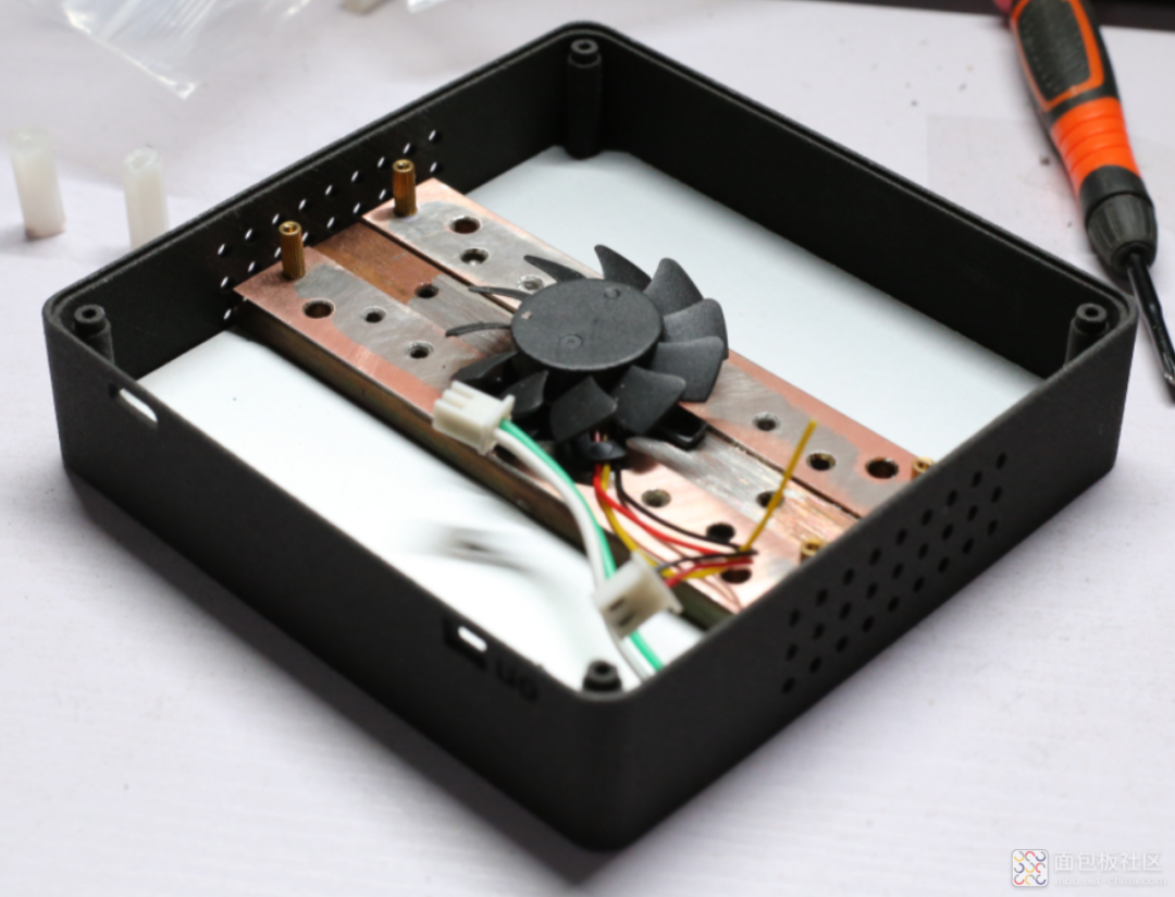 I connected the lamp board and fan connectors.
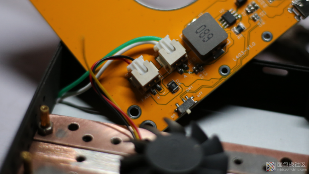 Then I placed the control board into the case.
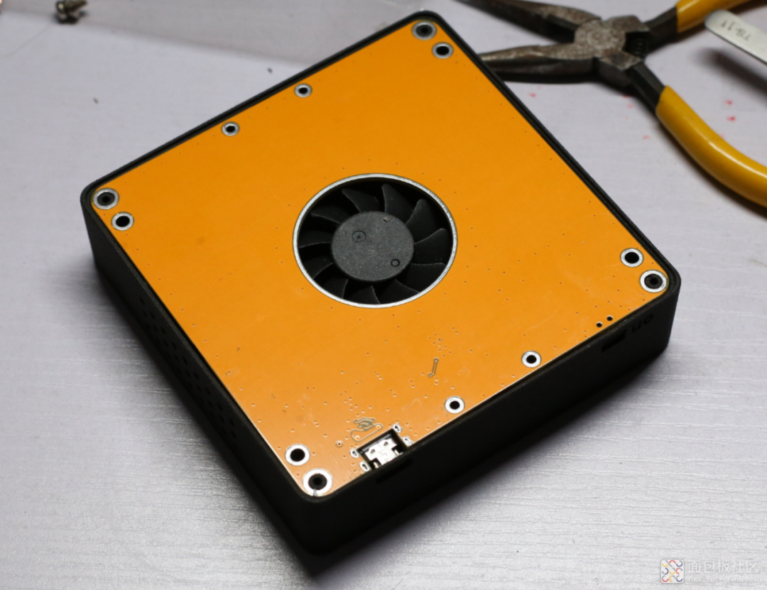 I closed the case and tightened the screws; the four screws are embedded in the case, and the UV lamp assembly is complete.
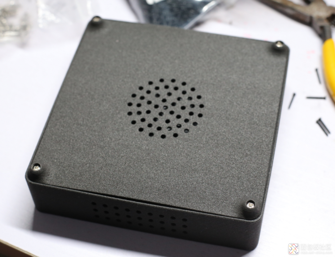 All done, let’s take a look at it in hand.
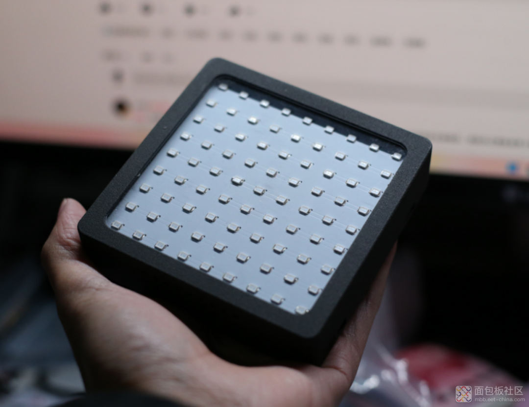 After assembling, let’s power it on and see how it works. All 81 LEDs lit up at once. When I took a direct shot, it lit up all at once, so I adjusted the aperture, shutter, and ISO for a long time to get this shot.
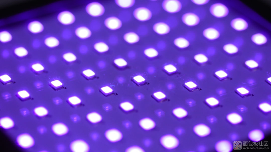
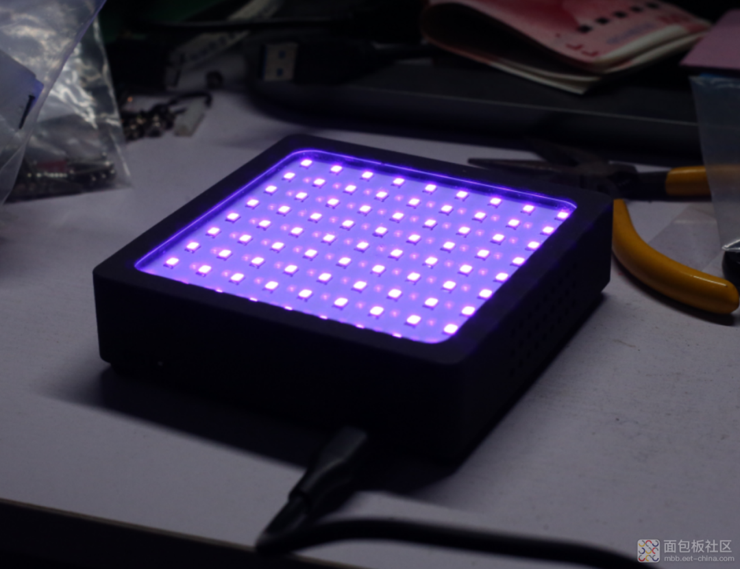 Let’s take a closer look with the camera. I find this type of UV lamp quite nauseating, so everyone should pay attention to protection.
 With the UV lamp done and the hydrogen peroxide arrived, I started the backlight method. Below is the transformation of the multimeter casing using the backlight method. The left side is after the backlight, and the right side is before, showing a clear contrast.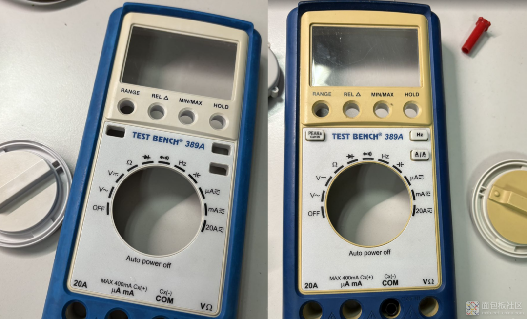
Scan to Join
Hardware Technology Exchange Group