EG3525 and SG3525 are both widely used PWM control chips that support push-pull / half-bridge topologies, commonly used in switch-mode power supplies, inverters, DC/DC converters, and other scenarios. EG3525 is a compatible upgrade model of SG3525, which enhances certain performance aspects through technical optimization while maintaining pin and functional compatibility. Below is a core comparison between the two and an analysis of the advantages of EG3525:
1. Key Parameter Comparison
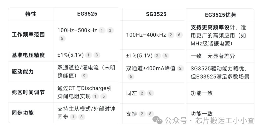
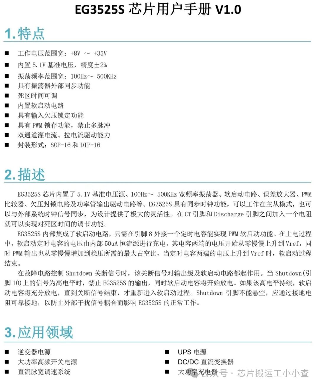
2. Core Advantages of EG35251. Wider Frequency Adaptability The oscillation frequency upper limit of EG3525 reaches 500kHz (SG3525 is 400kHz), making it more suitable for high-frequency switch-mode power supply designs (such as LLC resonant topology, RF power), which can reduce the size of magnetic components and improve power density. 2. Optimized Soft Start and Shutdown Control – Soft Start: Both chips achieve this through an external capacitor connected to pin 8, charged by an internal 50μA constant current source, but EG3525 emphasizes the linear increase of PWM duty cycle from 0 to Vref during the soft start capacitor voltage rise in the documentation, ensuring a smoother power-up. – Shutdown: EG3525 explicitly requires pin 10 to be reliably grounded through a grounding resistor to avoid interference from floating, enhancing noise immunity. 3. Compatibility and Cost Advantages EG3525 is designed to be fully compatible with the pin definitions of SG3525 (DIP-16/SOP-16 package), allowing for direct replacement without board modifications. In the context of domestic production trends, EG3525 has greater supply chain and cost advantages (supplied by manufacturers such as Yijing Microelectronics). 4. Functional Integration Flexibility Retaining all core functions of SG3525 (such as dead time adjustment, PWM latching, undervoltage lockout), while the **synchronous clock function** supports multi-chip collaborative operation, suitable for complex multi-phase power systems. 3. Actual Application Performance– High-frequency scenarios: The 500kHz upper limit of EG3525 makes it more efficient in resonant inverter power supplies (such as induction heating, ultrasonic power), with lower switching losses. – Anti-interference capability: The grounding design of the shutdown pin reduces the risk of false triggering, enhancing system reliability. – Domestic substitution: In industrial fields such as UPS and chargers, EG3525 has become a mainstream alternative to SG3525, with comparable performance and stable supply. 4. Selection Recommendations– Prefer EG3525: If the design involves high-frequency switching **(>400kHz)**, is cost-sensitive, or requires domestic supply chains, EG3525 is the better choice. – Continue using SG3525: If the project needs to strictly adhere to earlier designs (such as military, aerospace legacy systems), or relies on its ±400mA driving capability (extreme load scenarios), SG3525 can be retained. In general designs, the differences between the two are minimal; however, in high-frequency, compact power supply fields, EG3525, with its 500kHz frequency support, becomes a more modern choice.
Data sheets are as follows:
Introduction
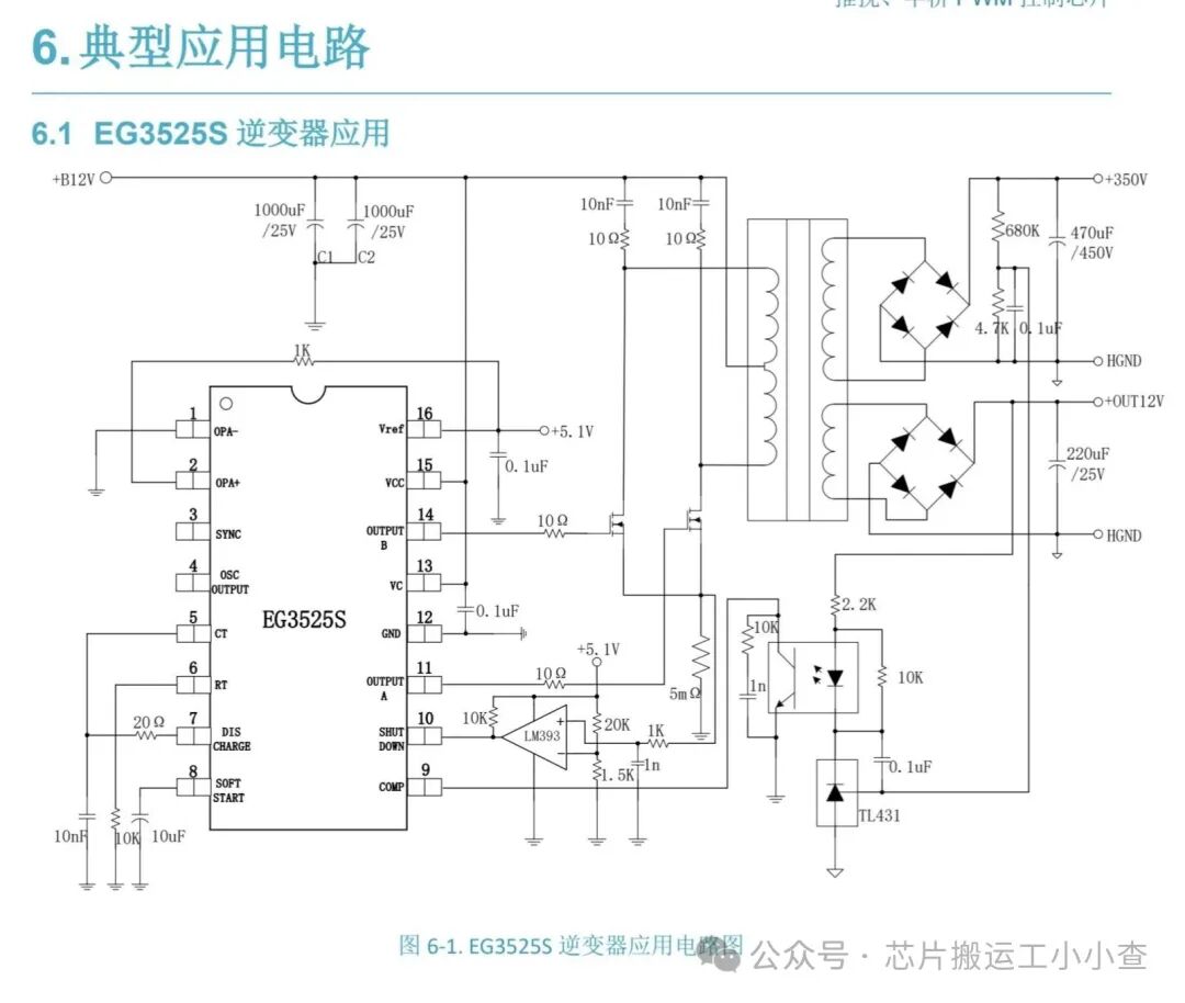
In this project, we will use the EG3525 chip with a PWM inverter circuit to create a 300W, 50/60 Hz inverter. This circuit will take a 12V DC power source from a 12V battery and convert it to a 220V, 300W PWM output. An inverter is an electronic device that converts direct current (DC) electricity into alternating current (AC) electricity. It is commonly used to power AC devices from DC power sources such as batteries or solar panels.
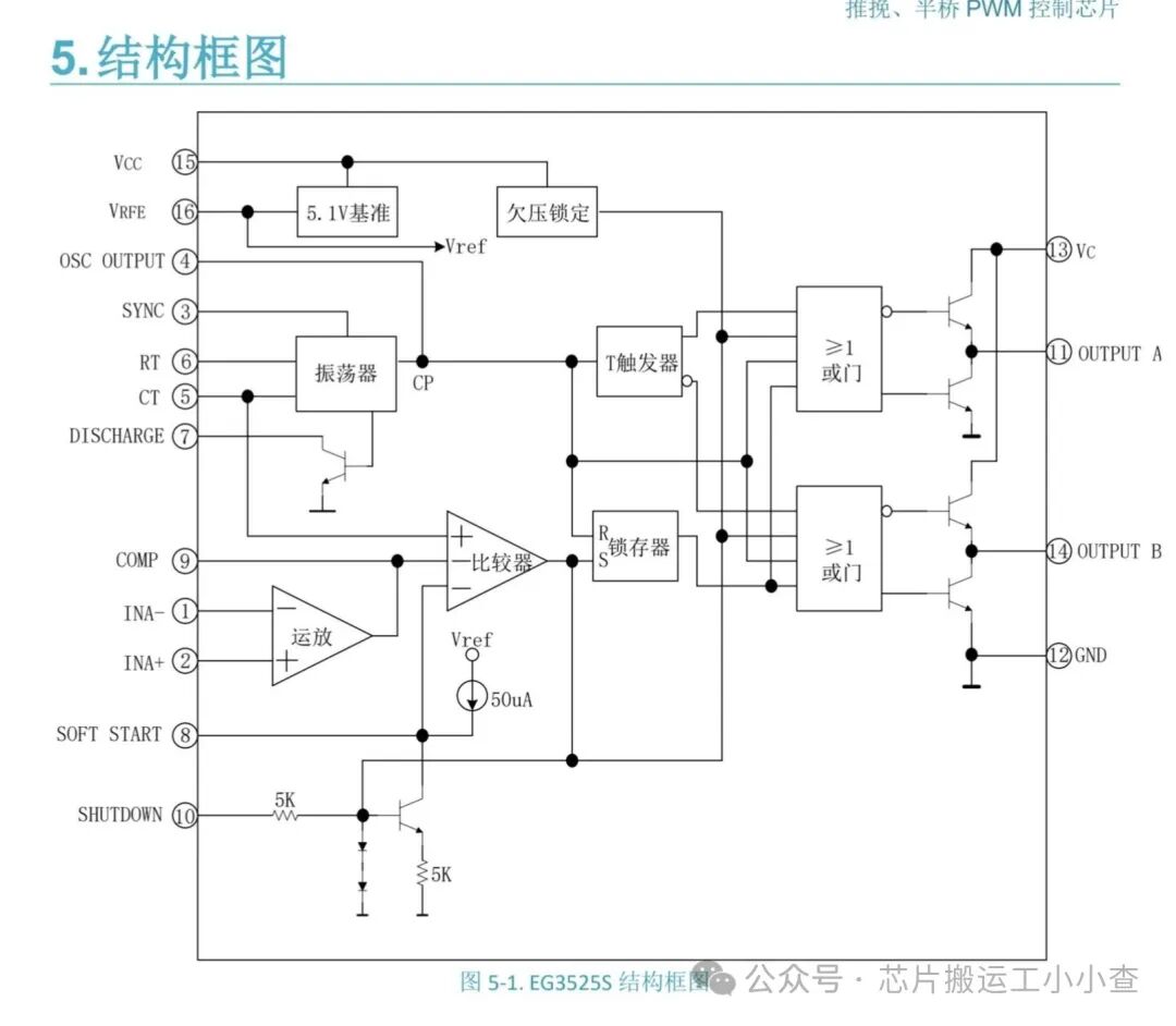
EG3525 is a pulse width modulation (PWM) control integrated circuit (IC) designed for switch-mode power supplies and inverters. It is intended to control the output voltage and frequency of DC-AC converters and can be used in various applications such as motor control, lighting, and uninterruptible power supplies (UPS). SG3525 provides a method to adjust the output voltage and frequency by varying the duty cycle of the PWM signal. It also includes protection features such as overcurrent and thermal shutdown.
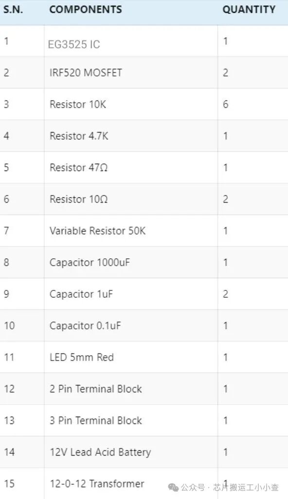
BOM
EG3525 Voltage Regulating PWM Controller
Design of EG3525 PWM Inverter Circuit
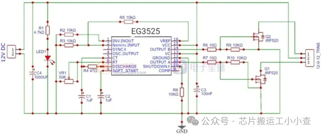
EG3525 can control the output voltage of the inverter. It can also drive MOSFET IRF520 connected to a transformer. Both MOSFETs are used as low-side connections. EG3525 has a built-in totem pole circuit to drive the low-side connected MOSFETs. A totem pole is an output driver circuit that converts one level of voltage to another level of voltage.
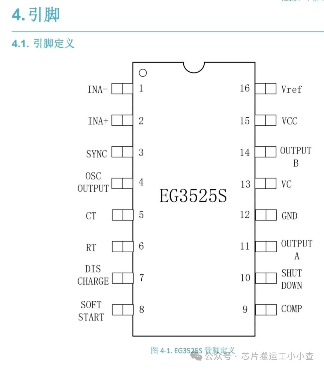
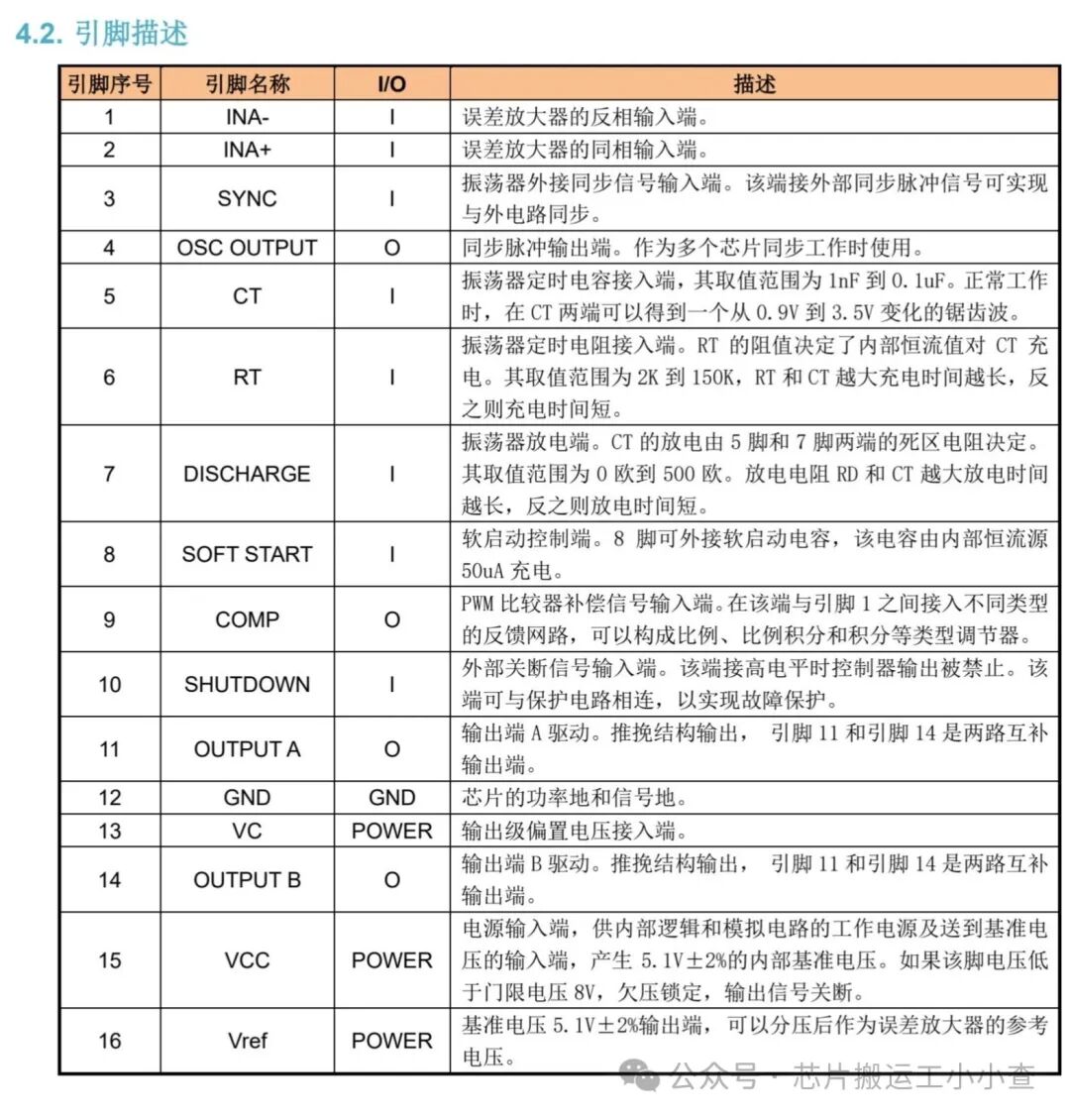
Pins 1 and 2 are the inputs of the onboard error amplifier. When the voltage on the inverting input (pin 1) is greater than the voltage on the non-inverting input (pin 2), the duty cycle decreases. When the voltage on the non-inverting input (pin 2) is greater than the voltage on the inverting input (pin 1), the duty cycle increases.
The frequency of the PWM depends on the timing capacitor and timing resistor. The timing capacitor (CT) is connected between pin 5 and ground. The timing resistor (RT) is connected between pin 6 and ground. The resistance between pins 5 and 7 (RD) determines the dead time. The frequency is related to RT, CT, and RD by the following relationship:
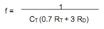
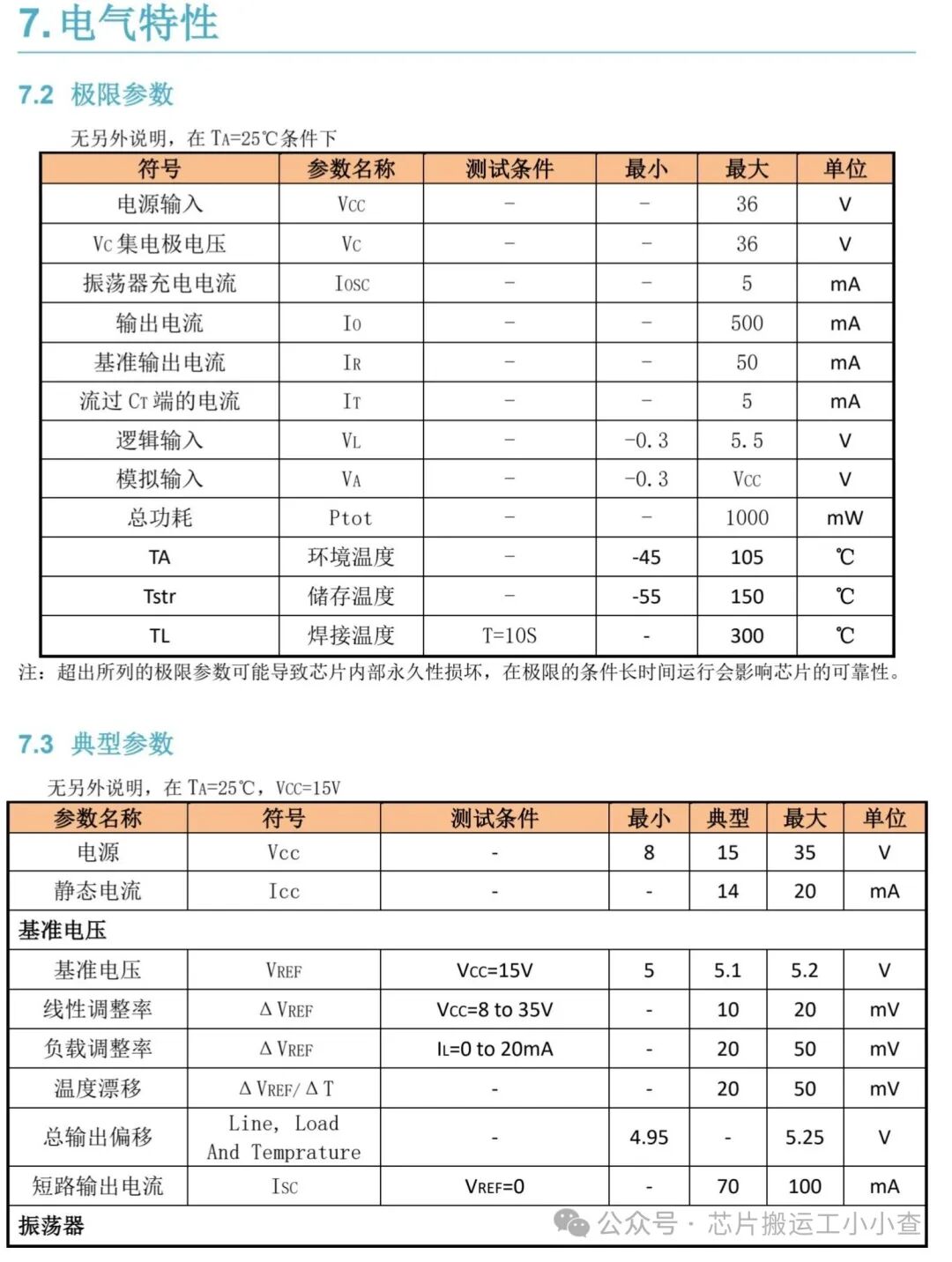
RT must be in the range of 2kΩ to 150kΩ. CT must be in the range of 1nF to 0.2µF. The oscillator frequency must be in the range of 100Hz to 400kHz. If you want to use it for a 50Hz inverter, you need a 50Hz driving signal. Therefore, the oscillator frequency must be 100Hz. The capacitor connected between pin 8 and ground provides the soft start function. The larger the capacitor, the longer the soft start time.
Pin 16 is the output of the voltage reference section. This reference is typically used to provide a reference voltage for the error amplifier to set the feedback reference voltage. Pin 15 is VCC—the power supply voltage for the EG3525. VCC must be in the range of 8V to 35V.
Pins 11 and 14 are the outputs from which the drive signals are obtained. They are the outputs of the internal driver stage of the EG3525 and can be used to directly drive MOSFETs and IGBTs. They have a continuous rated current of 100mA and a peak rated current of 500mA. Pin 10 is the shutdown pin. When this pin is low, the PWM is enabled. When this pin is high, the PWM latches immediately.
Note: This circuit is capable of producing 300W of PWM output. Use 75NF75 MOSFETs for this purpose. The maximum power of the 75NF75 MOSFET is 300W. Therefore, you need a 12-0-12V power transformer rated at 3A or 5A. In this case, the power supply should be 12V, 5A.
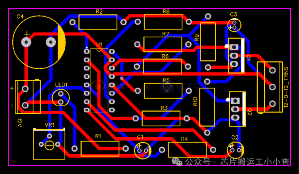
Gerber & PCB
The PCB drawn using EasyEDA is as follows:
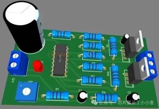
Circuit Assembly
The assembled circuit on the breadboard is as follows:
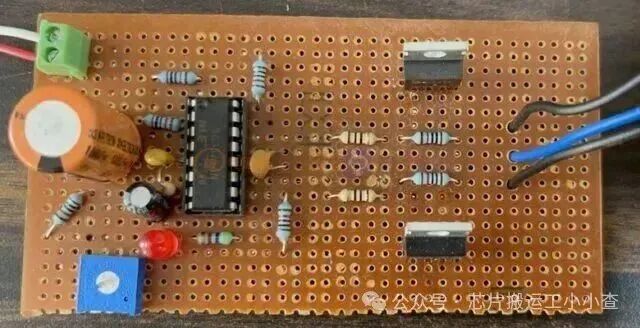
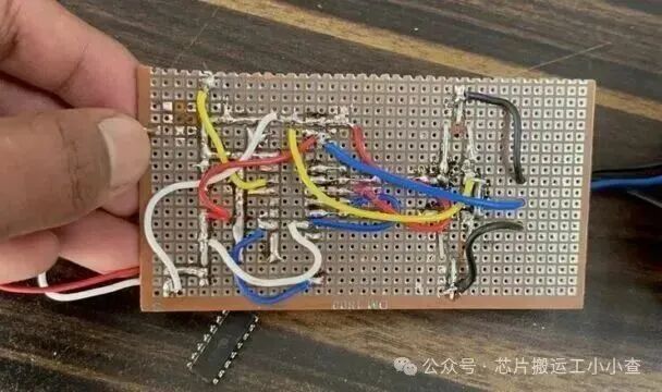
After assembling the components, you can connect a 12-0-12 transformer at the output. To achieve up to 300W of power, use a 12V transformer rated at 5A.
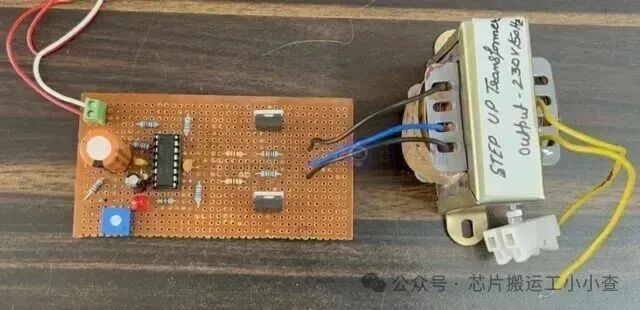
Connect a 12V, 7A lead-acid battery at the input for maximum power. You can also try using an 11.1V lithium polymer battery or any other power source with similar values.
Testing
Now let’s test the EG3525 inverter circuit. To test it, connect a load, such as a light bulb, CFL, or AC fan, to the output of the transformer.
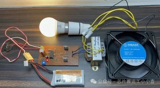
The light bulb lights up, and the fan starts immediately. You can try using other loads with higher rated power.
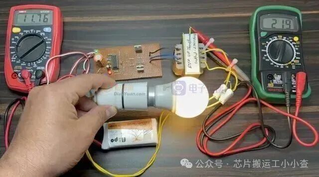
Using a multimeter, you can test the input and output voltages. At the input, it shows the battery voltage close to 12V, and at the output of the transformer, it shows the voltage of 220V.
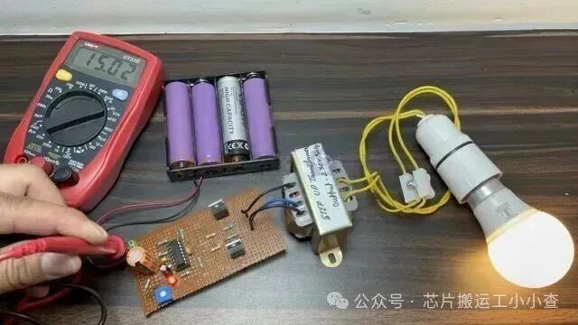
The inverter requires sufficient battery capacity as the power consumption of the battery can be significant. For testing, you can use a lithium polymer battery or lithium-ion battery, but for practical applications, use a 12V, 7Ah lead-acid battery. You can also adjust the output voltage of the inverter by tuning the 50K trimmer potentiometer on the PCB.
Some common applications of the 300W inverter include running small appliances in vehicles, powering lights or devices during power outages, or serving as a backup power source for outdoor activities or camping.