Digital power modules utilize various communication protocols such as I2C, SPI, CAN, UART, etc., as well as interaction protocols based on these, such as CANopen, SAE 1939, SMbus, PMbus, Modbus, etc.
This article simulates a Q&A session regarding I2C communication knowledge.
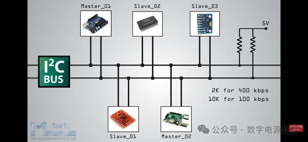
Question 1: What are the components of I2C communication, and what are their functions? Are pull-up resistors necessary?
Answer: I2C consists of two lines, SDA and SCL, which are the data and clock lines, respectively. Pull-up resistors are necessary because the SDA and SCL of the chip are open-drain designs, and the resistor values must match the corresponding baud rate.
 (This tests basic electrical knowledge; understanding hardware principles can help quickly locate issues during actual software and hardware debugging.)
Question 2: What is the difference between I2C and UART?
Answer: I2C supports one master and multiple slaves, while UART is point-to-point. In cases with many board-level devices, I2C is more suitable. I2C has a clock line, and strict baud rate matching is not required between master and slave devices.
 (This assesses familiarity with the significant differences between the two communication methods and their respective advantages and disadvantages.)
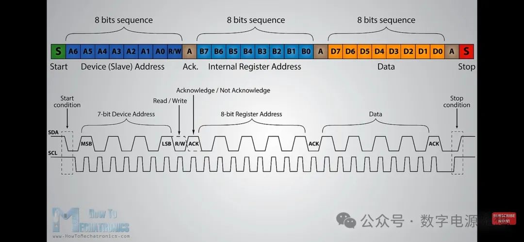
Question 3: What is the waveform of the START signal?
Answer: When both SDA and SCL are high, indicating the bus is idle, forcing SDA low while keeping SCL high signifies the START condition.
(This tests whether the candidate has actually measured bus waveforms and debugged bus timing.)
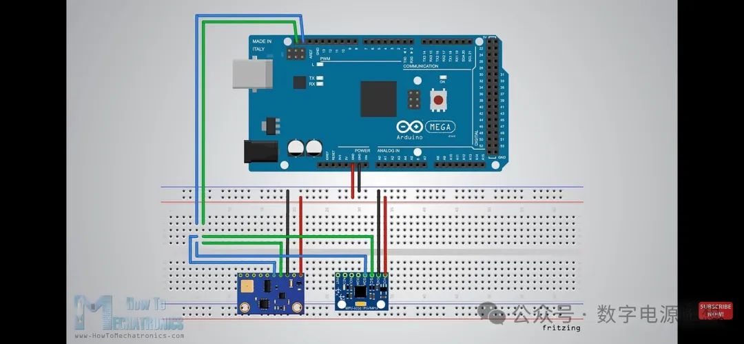
The images in this article are sourced from YouTube @How To Mechatronics How I2C Communication Works and How To Use It with Arduino.
If you find this article helpful, feel free to follow my public account, like, recommend, and leave comments in the lower right corner. Thank you!