7-segment displays are inexpensive and easy to drive, capable of showing numbers 0-9, characters A, b, C, d, E, F, P, q, L, etc. They are widely used in electronic products for simple data display. For example, in temperature controllers for temperature and setting parameter display, electronic clocks for time display, and elevators for floor display.
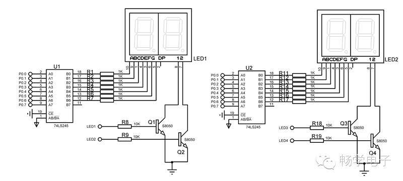
I used to think that the driving circuit for 7-segment displays was quite simple, and since I had never used it in projects, I did not analyze it in depth. Recently, I was working on a microcontroller textbook titled ‘Principles and Applications of Microcontrollers—Based on Proteus and Keil C’, for which I designed a supporting experimental board. The experimental board has two 2-digit common cathode 7-segment displays for simple information display. Initially, I designed the circuit as follows:
After completing the circuit soldering, I found that the brightness of the display was very low during dynamic display tests. I suspected that the resistor values might not be suitable. After researching a lot of information online, I replaced the resistor values, and the problem was resolved. Now I summarize the estimation process of the resistor values as follows.
The I/O port driving capability of the 51 microcontroller is limited, so I added a 74LS245 between the P0 port and the segment code of the display to enhance the port driving capability. Resistors R1~R7 and R11~R17 serve to limit current to protect the display. When the display lights up, the common current is very high. If the common terminal is directly connected to the microcontroller pin, a large current will flow into the microcontroller pin, potentially damaging it. Therefore, I added transistors Q1, Q2, Q3, and Q4. The transistors act as switches, allowing most of the display driving current to flow from C to E into the power ground, with a small portion flowing into the microcontroller pin. The transistors operate as switches in the saturation and cutoff regions. When the transistors are on, the display lights up, and the transistors work in the saturation region.
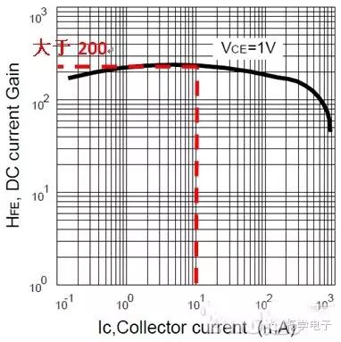
First, I calculate the maximum segment current. With 4 displays, each containing 8 segments, and an average current of 3mA per segment, the maximum current is 4*8*3=96mA, approximately 100mA. From the relationship between collector current and amplification factor, we can see that when Ic=100mA, Hfe>200. Theoretically, Ib=0.5mA is sufficient to saturate the transistor. When saturated, the transistor voltage drop Vbe=0.7V, so R=(5-0.7)/Ib=4.3K. To ensure reliable conduction of the transistor, a general base protection resistor R is taken as 1~2K.
Next, I calculate the value of the segment current limiting resistor. First, I calculate the segment current. Generally, the forward voltage drop of a red LED is about 1.6V, and for a green LED, it is about 1.8V. During static display, the segment current is approximately 3mA. When 4 displays are dynamically showing in rotation, to maintain the same brightness as in static display, the driving current needs to be increased by 4 times, so the dynamic display segment driving current must reach 3*4=12mA. Thus, R=(Vcc-1.6)/(3*4)=0.28K, so using a 300Ω resistor is about right. The value of this resistor directly affects the display brightness of the segment.
According to the derivation above, after replacing the resistor, the brightness of the display increased significantly.