1. Resistance Variation with Temperature
The electrical conductivity of metals depends on the mobility of conducting electrons or the electron gas. When a voltage is applied across a metal, electrons move from the negative to the positive terminal. During the movement of electrons, the non-ideal states of the metal’s crystal structure interfere with their motion. These non-ideal states include atoms outside the lattice or not in the lattice, atoms at the boundaries of the crystal, and atoms between the lattices. Due to the structural misalignment of the non-ideal states in the metal’s crystal structure, they exert a constant resistance on the motion of electrons that is independent of temperature. As the temperature increases, the vibrations of atoms near the equilibrium position in the metal lattice intensify, which restricts the movement of conducting electrons. The atomic vibrations increase linearly with temperature. A rough estimate shows that resistance increases proportionally with temperature. At this point, we refer to this conductor as a PTC resistor, which has a positive temperature coefficient.
When using this effect for temperature measurement, it is desirable for the conductor to have a high temperature coefficient, allowing for as large a change in resistance as possible with temperature variations. On the other hand, it is best if the temperature coefficient does not change significantly over a long period. Additionally, the temperature coefficient should not depend on temperature values and pressure values, nor be affected by chemical actions.
Generally, the relationship between temperature and resistance is not linear but can be described by a higher-order polynomial:
Formula:

R0 represents the nominal resistance measured at a specific temperature. The specific form of the higher-order polynomial (such as T2, T3, etc.) is related to measurement accuracy. The coefficients A, B, etc., depend on the resistance material and are used to clearly indicate the relationship between temperature and resistance.
2. Platinum Resistance
Currently, platinum is widely used as a resistance material in industrial measurements. Its advantages include high chemical stability, ease of processing (especially for wire manufacturing), the ability to achieve high purity, and good reproducibility of electrical characteristics. The European standard EN60751 details these properties, so platinum resistance sensors have universal interchangeability, which is unmatched by other temperature sensors.
The standard includes the laws of resistance variation with temperature presented in the form of standard value reference tables, the nominal resistance values at various reference temperature points, and allowable error limits. The standard also specifies that the temperature range is from -200°C to 850°C, and provides standard value reference tables for the following two temperature ranges:
-200°C to 0°C
0°C to 850°C
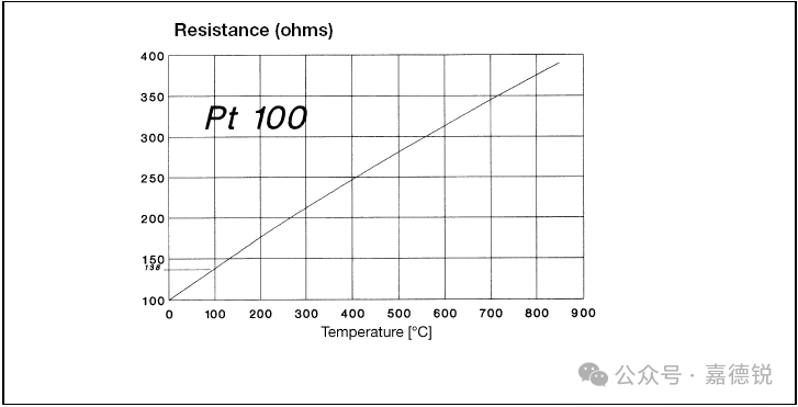
Figure: Characteristics of Pt 100 Temperature Sensor
A cubic polynomial covering the temperature range of -200°C to 0°C:
Formula:

A quadratic polynomial covering the temperature range of 0°C to 850°C:
Formula:

The values of the coefficients are as follows:
A = 3.90802×10⁻³ · °C-1
B = – 5.775×10⁻⁷ · °C-2
C = – 1.2735×10⁻¹² · °C-1
R0 is defined as the nominal value or nominal resistance value, which is the resistance at 0°C. The nominal value defined in EN 60751 is 100Ω, so we also refer to this resistance as Pt100 resistance. It is also permissible to use multiples of this value as nominal values, so the nominal resistance can also be 500Ω and 1000Ω. The advantage of resistors with nominal values of 500Ω and 1000Ω is high sensitivity, meaning that the resistance changes more significantly with temperature variations. (Pt100: approximately 0.1Ω/°C; Pt500: approximately 2.0Ω/°C; Pt1000: approximately 1.0Ω/°C).
The Pt10 resistor defined in the standard is rarely used due to its low sensitivity. The working temperature range of Pt 10 is above 600°C. Resistors with smaller nominal values (e.g., 25Ω, 10Ω, 5Ω and 0.25Ω) are mainly used in precision thermometers, which must meet the requirements of ITS 90 and are applied in situations where measurement uncertainty requirements are very low. Due to the precision and high quality of the metal wire structure used, such thermometers are not suitable for industrial applications.
The standard also defines another parameter, the average temperature coefficient between 0°C and 100°C. This parameter describes the average resistance change based on the nominal resistance value at 0°C.
Formula:

R0 is the resistance value at 0°C, R100 is the resistance value at 100°C, and 100 is the temperature difference.
The spectral purity of platinum has an α value of 3.925×10⁻³Ω/°C. The temperature coefficient of platinum resistance sensors specified in EN 60751 deviates from this value. This is because the platinum used in platinum resistors is generally artificially doped with other materials. This is done to minimize contamination of the platinum resistance thermometer during manufacturing and in environments above 100°C, ensuring its long-term stability.
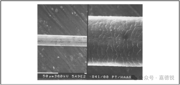
Figure: Comparison of Platinum Wire (left) and Hair (right)
For industrial applications, platinum resistance has sufficient long-term stability. However, for precision thermometers with stability reaching 0.001°C, even very small diffusion effects are significant. For this reason, the relatively thick metal wire used in precision thermometers reaches a diameter of 0.25mm. To reduce the size of temperature sensors, precision thermometers with a measurement range above 600°C typically use nominal values of 25Ω or 10Ω. During the manufacturing process of the sensors, conventional techniques can produce metal wires with diameters less than 30 µm. (In comparison, the thickness of human hair is approximately 100 µm).
3. Calculating Temperature Using Resistance
When used as a thermometer, platinum resistance sensors often determine the temperature value based on their sensor resistance value. However, the above formula only reflects the change in resistance with temperature and does not indicate how to derive the temperature value from the measured resistance value. When the temperature is above 0°C, according to EN 60751, a straightforward formula can be used to calculate the temperature from the resistance value.
Formula:

R: Measured resistance value, unit: ohm
t: Calculated temperature, unit: °C
R0, A, B: Parameters specified in IEC 60 751
For temperatures below 0°C, it is not possible to derive a straightforward inverse function formula. To obtain the temperature value corresponding to the measured resistance value, an approximate numerical method must be employed. The Newton approximation method is sufficient for the required accuracy. Starting from an arbitrary temperature t0, iterative values can be calculated repeatedly using the following formula:
Formula:
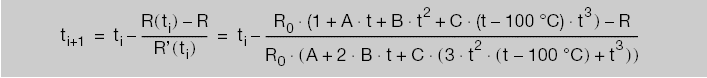
When the difference between two consecutive iterative values does not exceed the required accuracy, the iterative calculation can be terminated.
For example:
The measured resistance value is R = 87.618Ω.
The initial temperature value t0 = -5°C.
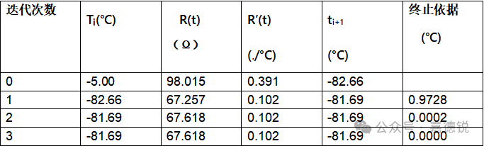
Table: Example of Complete Iterative Calculation Process
The above example shows that after the first step of iteration, the temperature is already determined, with an accuracy of 0.01°C.
Of course, the temperature is also determined by the standard value table. If intermediate values are not provided in the standard value table, they can be calculated using linear interpolation. To calculate the temperature value t from the resistance value R, it is necessary to know the upper and lower pairs of temperatures corresponding to the resistance values close to R:
Formula:

For example:
The resistance is 129.53Ω, and we will calculate the temperature.
From the reference table, the data obtained is:R1 = 129.37. t1 = 76°C
R2 = 129.75. t2 = 77°C
Formula:

1. Allowable Error Limits
EN 60751 defines two different allowable error grades:
A grade:Δt= ±(0.15 + 0.002 × t)
B grade:Δt= ±(0.30 + 0.005 × t)
where t is the absolute temperature, unit: °C
A grade applications have a temperature range of -200°C to +650°C, and are only applicable to platinum resistance thermometers using 3-wire or 1-wire systems.B grade applies to the entire defined temperature range, i.e., -200°C to +850°C.
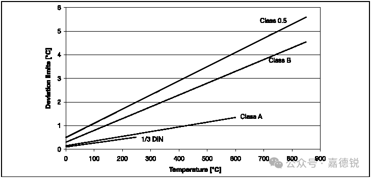
Figure: Allowable Error Limits of Pt 100
For example: For a B grade Pt 100 platinum resistance thermometer, at 200°C the measurement error is:
t = ±(0.30 + 0.005×200)°C= ±(0.30 + 1)°C= ±1.3°C
2. Extended Allowable Error Grades
The allowable error grades specified in the standard are often insufficient. This is because the requirements for measurement accuracy gradually increase with the need for improved product quality. As a result, users and manufacturers of platinum resistance thermometers have agreed to create a new allowable deviation grade that is close to B grade. In other cases, the opposite requirement may arise, where many users are very cost-conscious when the extended allowable error grade is already sufficient for them. It is worth emphasizing that increasing the allowable error of the sensor does not compromise the excellent characteristics of platinum resistance temperature sensors. Long-term stability, reproducibility, and interchangeability of the sensors will be fully maintained. In addition to the two allowable error grades specified in the standard, JUMO also defines additional allowable error grades that can provide users with options for low accuracy or high accuracy, thus matching actual applications.
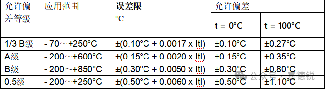
Table: Allowable Error Grades of Resistance Thermometers
Stricter allowable error grade 1/3B grade is formed based on the standard B grade, with the error limit increased to one-third of the B grade error limit. The working temperature range of this allowable error grade is typically specified as -70°C to +250°C. Such restrictions are necessary because the nominal values and linear characteristics of the sensors can fluctuate due to manufacturing processes. To classify the sensors into different grades, they must be tested within the range of 0°C to 100°C. Because typically only two measurement points are used during testing, it is not possible to derive the parameters of the quadratic equation. Furthermore, extrapolating the temperature range increases the measurement uncertainty of this measurement method. Therefore, when using 1/3B grade, the temperature range is strictly limited. It is worth noting that the usable temperature range of the sensor or thermometer is not affected by the working temperature range specified by 1/3B grade; it merely means that outside the working temperature range specified by 1/3B grade, the allowable error is legally invalid, and there is no way to guarantee that the sensor’s error has not changed.
 For more information or technical consultation, please follow our public account or add the WeChat below