Today, we will introduce the widely used SPI communication between PCB boards, striving to minimize the introduction of overly textual definitions and instead use straightforward language to explain.
Definition:
SPI (Serial Peripheral Interface) is a type of serial synchronous communication, which is mostly full-duplex (but it can also be half-duplex), primarily used in chips such as EEPROM, FLASH, ADC, and DAC.
Hardware characteristics: four-wire, three-wire, six-wire:
SPI is generally four-wire, consisting of four lines: the well-known CLK (clock line), CS (chip select line), MOSI (Master Out, Slave In), and MISO (Master In, Slave Out). In this case, it usually operates in full-duplex mode.This is standard SPI.
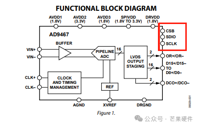
However, sometimes there is a three-wire configuration, where SCLK, CS, and SDIO combine the data signals into two lines, operating in half-duplex mode. Many of ADI’s ADCs use this unconventional SPI.
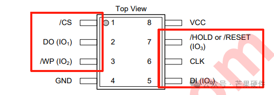
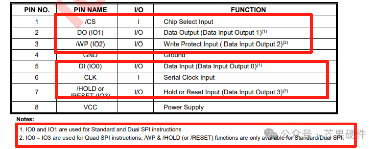
In the six-wire configuration, two additional I/O lines are added: CLK, CS, IO0, IO1, IO2, IO3, allowing simultaneous transmission of four data lines, with 4 bits of data transmitted in one clock cycle. Its main feature is the ability to provide higher speeds; at the same clock frequency, QSPI theoretically achieves a transmission rate four times that of SPI, reaching up to 200MHz, which is significantly higher than the maximum rate of SPI (50MHz). This explains why this transmission method is commonly used in NOR flash. In this case, it operates in half-duplex mode. Because it can transmit four data lines, it is also known as QSPI (Q stands for Queued). We often see QSPI in some NOR flash from Winbond. Additionally, similar to QSPI is Dual SPI, which modifies the full-duplex transmission of standard SPI to half-duplex. It changes the original MOSI (Master Out, Slave In) and MISO (Master In, Slave Out) data lines into bidirectional data lines, now referred to as SIO0 and SIO1 (Serial I/O 0 and Serial I/O 1). In one clock cycle, it transmits 2 bits of data, thereby increasing the data transmission rate. This part is clearly reflected in the Winbond specifications below. In fact, whether it is Dual SPI or QSPI, the goal is to convert full-duplex to half-duplex, which can significantly improve communication efficiency.
Connection methods for SPI:
When multiple slaves can use a single SPI, the slaves can be connected in either a conventional mode or a daisy chain mode.
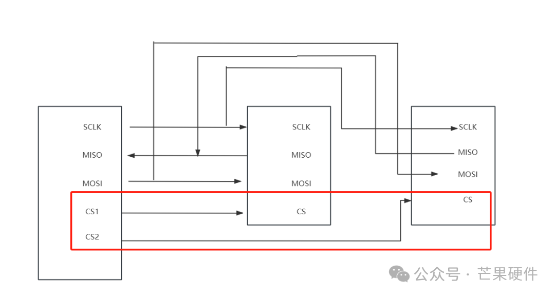
Conventional mode connection: The master provides a separate chip select signal for each slave. Once the master enables (pulls low) a specific chip select signal, that slave can operate.
Daisy chain mode connection: All slave chip select & clock signals are connected together, and data propagates from one slave to the next.
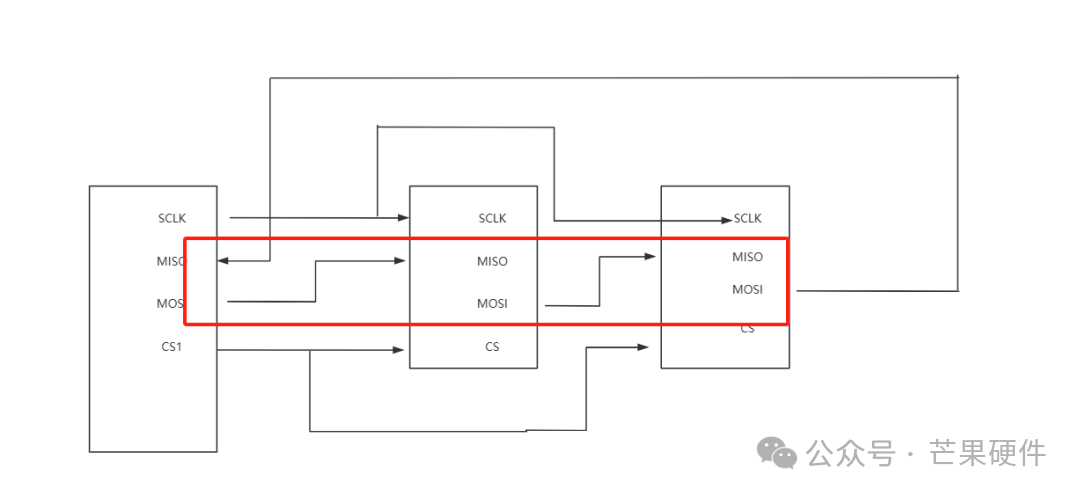
Among these two connection modes, the first mode is generally used more frequently, but when the MCU ports are limited and there are many slaves, the advantages of the daisy chain mode become apparent. In such cases, we often use the daisy chain topology.
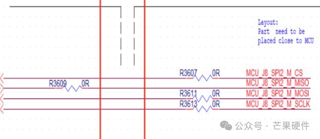
Series resistors in SPI: Many times we see a 22-ohm, 33-ohm, or 0-ohm resistor in series with the SPI signals like MISO and MOSI. First, it should be noted that when we use standard SPI, the rate is not high, generally around 5M. At this point, these resistors are not for impedance matching, but to eliminate ringing. Because the SPI I/O ports are generally push-pull structures, their output impedance is very low, and the PCB wiring will have some parasitic inductance and capacitance. If the output signal has too fast rising or falling edges, ringing will occur.