
Click the blue text to follow us

The I2C bus is a two-wire serial expansion bus introduced by Philips for connecting IC devices. Due to its advantages such as fewer pins, simple hardware, ease of establishment, and strong scalability, many mainstream device products use the I2C interface as the standard for data or control information.
In the previous article, Digital IC Design – In-Depth Understanding of the I2C Serial Bus (Part I), we mainly introduced the structure, basic characteristics, and data transmission rules of the I2C bus.This article continues to introduce the addressing format, four operating modes, arbitration, and clock synchronization of the I2C bus.
Addressing Format
There can be many devices connected to the I2C bus, and each device connected to the I2C bus has a unique address for the master to address.The commonly used addressing formats for the I2C bus are 7-bit addressing format, 10-bit addressing format, and broadcast call.
1
7-bit Addressing Format
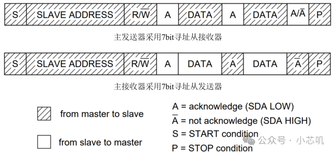
In the 7-bit addressing format,the first byte after the START condition contains the 7-bit slave address and the R/W bit, where R/W is in the least significant bit (LSB) to determine the direction of data transmission.
-
R/W = 0: The master sends data.
-
R/W = 1: The master receives data.
When the master sends the address, each slave on the bus compares this 7-bit address code with its own address. If they match, the slave considers itself to be addressed by the master. Then, based on the R/W bit, it determines whether it is a transmitter or a receiver and responds accordingly. After addressing is complete, data transmission begins between the master and the slave. After the transmission is complete or a NACK is received, the master sends a STOP condition to end the data transmission.
2
10-bit Addressing Format
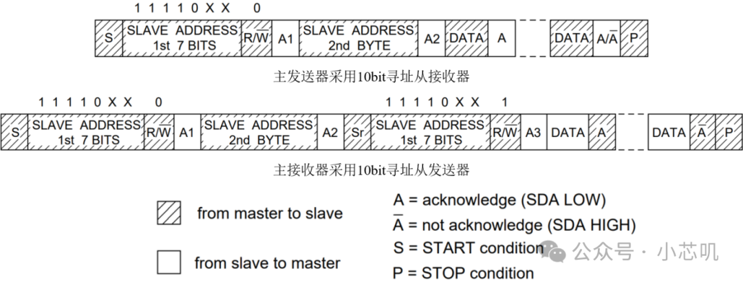
In the 10-bit addressing format,the first byte after the START condition is 11110b, with the high two bits of the 10-bit slave address and the R/W bit; the second byte contains the remaining 8 bits of the 10-bit slave address. The slave must send an acknowledgment after each byte transmission.
The R/W bit in the first byte must be 0, meaning the master sends data. If the master needs to receive data sent by the slave, thenafter sending the second address byte, it uses the RESTART condition to change the direction of data transmission. The previously addressed slave will remember that it was addressed, so after the RESTART condition, it will check if the address of this byte matches itself and R/W=1. If it matches, this slave will realize it has been addressed and will act as a transmitter.
3
Broadcast Call
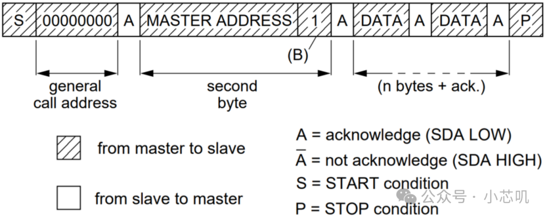
Broadcast call (General Call) is used to address every device connected to the I2C bus. If a slave does not need the data provided in the broadcast call, it can ignore this addressing by sending a NACK. If it needs the data in this broadcast call, the slave will respond with an ACK and act as a receiver.The significance of broadcast call addressing is specified in the second byte.
Why is a broadcast call needed? Some devices, such as keyboard scanners, do not know in advance which slaves to send data to, so they cannot configure a specific slave address. Therefore, they can only send a broadcast call along with their own address, allowing the system to identify them.
Operating Modes
The I2C module can be defined as a “master” or “slave”, “transmitter” or “receiver” based on its function. Therefore, devices on the I2C bus can choose one of the following four modes:
-
Master Transmitter Mode
-
Master Receiver Mode
-
Slave Transmitter Mode
-
Slave Receiver Mode
All masters start in the “Master Transmitter” mode, as the master needs to send address information first.Thus, the “Master Receiver” mode can only be entered from the “Master Transmitter” mode.Depending on the configuration, data transmission can use any of the addressing formats mentioned above. The master is responsible for generating clock pulses on SCL, and when acting as a transmitter, it shifts out serial data bit by bit to SDA; when acting as a receiver, it shifts in serial data bit by bit from SDA.
The I2C module defaults to operate in slave mode, and all slaves start in the “Slave Receiver” mode, as the slave needs to receive the address information on the SDA line first.Thus, the “Slave Transmitter” mode can only be entered from the “Slave Receiver” mode.With the clock pulses on SCL, when acting as a receiver, the slave shifts in serial data bit by bit from SDA; when acting as a transmitter, it shifts out serial data to SDA bit by bit.
Arbitration and Clock Synchronization
1
Arbitration
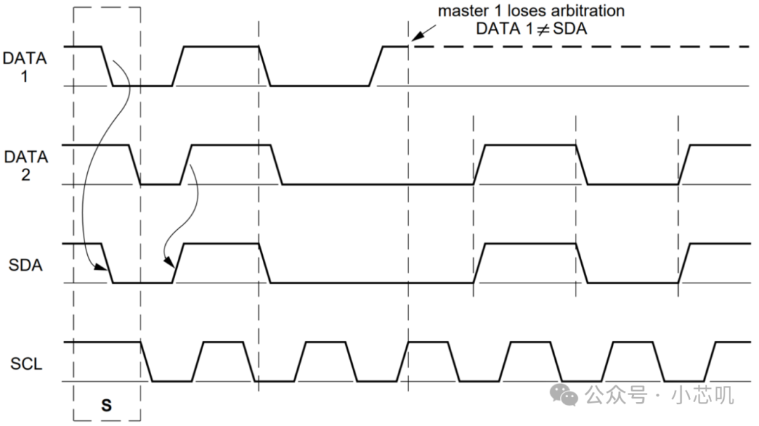
If two or more masters initialize data transmission simultaneously, arbitration can prevent data corruption.Due to the “wired AND” property of the I2C bus, a low level is the dominant level; as long as one device pulls SDA low, the entire bus will be pulled low.When multiple masters believe the I2C bus is idle and start communication, they will determine the ownership of the bus when they encounter the first differing bit on SDA. The master that loses arbitration will switch from “Master Transmitter” mode to “Slave Receiver” mode.
The arbitration process between two masters
For example, the first byte sent by master 1 is 8’b0011_0010; the first byte sent by master 2 is 8’b0010_0011. When sending to the 3rd bit, SDA is pulled low by master 2, and master 2 gains control of the I2C bus.
Ifthe first byte sent by multiple masters is the same, arbitration continues in the subsequent bytes, until a differing bit occurs in the transmitted data.
2
Clock Synchronization
Under normal circumstances, only one master generates the SCL clock signal. However, during arbitration, multiple masters may generate SCL simultaneously, so the clock must be synchronized to compare the output data.
Utilizing the “wired AND” property of SCL, the device that first generates a low-level period on the SCL line will pull the entire bus low, forcing other masters to start their low-level periods. Based on the longest low-level period, the SCL line is kept low, and other masters must wait until the SCL line is released before they can start their high-level periods.Thus, after clock synchronization, the slowest device determines the length of the low-level period, while the fastest device determines the length of the high-level period.
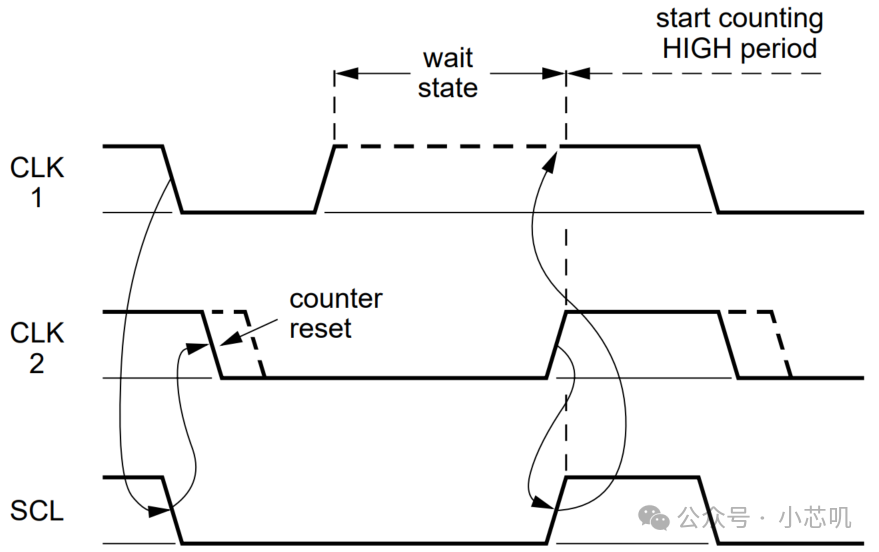
Clock Synchronization
Thank you for reading my article. If you find it useful, please give me afollow! Let’s chat again next time.
>/ Author: Xiao Xin Ji