A pull-up resistor connects a signal line to a fixed high level VCC, keeping the signal line in a high state when idle, which is known as a pull-up resistor.
The pull-up resistors on a bus have different roles; for example, the pull-up resistors for I2C are determined by the internal structure of the I2C port, while the pull-up resistors for RS485 and CAN buses are used for terminal matching. So, do these different buses require pull-ups, and what considerations are there for choosing their values?
Yes, the selection of these resistor values is based on theoretical principles. If the resistor value is not chosen correctly, it can cause anomalies. For instance, there was a case where the pull-up resistor for I2C was set to 10K, while the application required I2C to run at a high speed of 400KHz. Clearly, such a pull-up resistor cannot meet the 400kHz high-speed requirement, and communication errors are inevitable.
For RS485 and CAN buses, the use of pull-up resistors needs to be flexible based on the field conditions. Even if two applications have the same number of nodes, due to differences in wiring and connected devices, the required matching resistors may differ. The theoretical calculated values can serve as important reference points.
 What Is the Role of Pull-Up Resistors in I2C and How to Determine Their Values?Objective: Ensure normal communication.
It is commonly said that I2C requires pull-up resistors, but why are they necessary?
Firstly, it is determined by the I2C protocol itself, where both lines maintain a high state when idle, enabling the “AND” functionality.
Secondly, the internal structure of the device, as shown in Figure 1, indicates that the SCL and SDA pins cannot provide a high level internally and must rely on an external high level. Currently, some devices support pull-up functionality in open-drain mode, and the chip can be configured to pull-up mode (it is recommended to use external pull-up resistors).
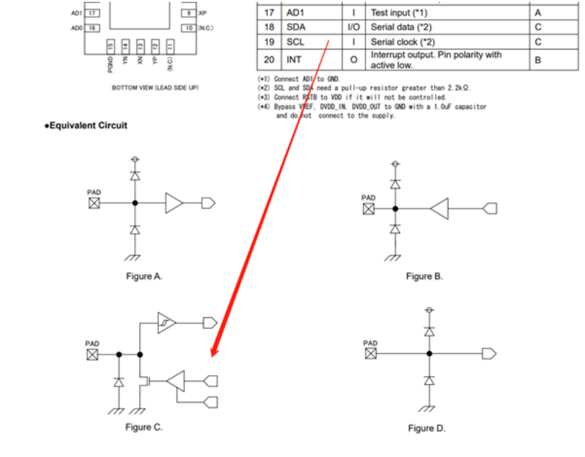
Figure 1 Equivalent Circuit of I2C Port Internal Structure
How to Determine the Value of I2C Pull-Up Resistors?
Consider the IO sinking current; the resistance value cannot be too small. Typically, in standard mode at 100KHz, the sinking current should not exceed 3mA,
VOL should not exceed 0.4V. If the pull-up resistor is connected to 3.3V, the pull-up resistor value should be greater than 1k.

Substituting Vdd = 3.3, Vol(max) = 0.4, Iol(max) = 3, we get Rmin = 966Ω.
Considering rise time, the resistance value cannot be too large. The high level is provided by the external pull-up resistor, and the resistor and bus capacitance form an RC network. If the resistance is too large, the charging time will be too long, causing the signal to rise slowly and not reach the high level within the specified time, leading to data errors. For I2C systems, the rise time and fall time should be measured when the pull-up voltage is at 30% to 70%. The bus capacitance is 100pF, and the maximum rise time is 300ns.

Substituting Tr = 300, Cb = 100, we calculate Rmax = 3.54kΩ.
Based on the above calculations, the value of the pull-up resistor should be between 966 and 3.54k. In practical engineering design, it is not always designed exactly to this value; typically, values like 2.2k, 3k, and 4.7k are selected.
To resolve I2C communication issues, it is recommended to capture the I2C waveform, observe the rise/fall times on the bus, analyze factors like bus capacitance and pull-up resistance, and conduct a comprehensive analysis in conjunction with the driving code.
#Recommended Reading#The Seven Deadly Sins of I2CUnderstanding SPI in SecondsCan You Distinguish SPI, I2C, UART, I2S, GPIO, SDIO, CAN?