Comparison of I2C and SPI Communication Protocols
In microcontroller development, peripheral expansion is an inevitable task, such as connecting sensors, displays, or memory. Both I2C and SPI are commonly used communication protocols, each with its own advantages and disadvantages, suitable for different scenarios. This article will help you understand the basic concepts, hardware connections, code examples, and practical application cases of these two protocols, assisting you in selecting the appropriate communication method based on project needs.
What are I2C and SPI?
I2C (Inter-Integrated Circuit)
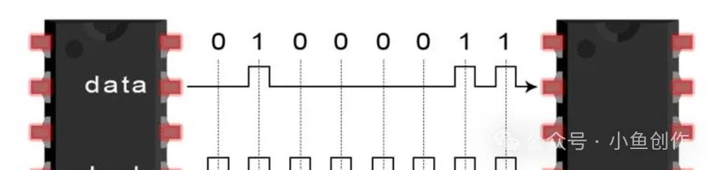
I2C is a protocol that uses two signal lines (SCL and SDA) to achieve device communication, commonly used for short-distance connections between microcontrollers and peripherals. It adopts a master-slave architecture, where one master can control multiple slaves, distinguished by device addresses.
Characteristics:
-
Advantages: Only requires two wires, saving pins; supports multiple slaves, strong scalability.
-
Disadvantages: Communication speed is relatively slow (100kbps~3.4Mbps), hardware implementation is more complex.
SPI (Serial Peripheral Interface)
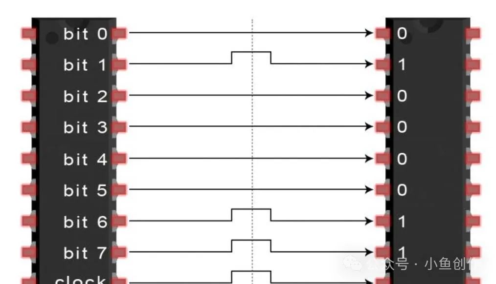
SPI is a full-duplex communication protocol that requires four signal lines (SCLK, MOSI, MISO, CS/SS) to achieve data transmission. It adopts a master-slave mode, but each slave requires an independent chip select signal (CS).
Characteristics:
-
Advantages: Communication speed is fast (up to tens of Mbps), hardware implementation is simple.
-
Disadvantages: Requires more pins; more chip select lines are needed when multiple slaves are present.
Analogy Explanation:
You can think of I2C as a “ shared intercom channel ” where everyone has their own code (address) to communicate; whereas SPI is like “ making a phone call ”, one-to-one communication where both parties can speak simultaneously.
Hardware Connections of I2C and SPI
I2C Hardware Connection
The two signal lines of I2C are:
-
SCL (Clock Line): The clock signal generated by the master, used to synchronize data.
-
SDA (Data Line): Bidirectional data transmission line.
Multiple slaves are distinguished by device addresses and connected to the same SCL and SDA lines. Note the use of pull-up resistors, usually around 10kΩ (can be adjusted based on the length of the line).
Example Circuit Diagram:
1 Master (Master) -> SCL -> Slave 1
2                -> SDA -> Slave 2
3                (Connect pull-up resistors on both lines)
SPI Hardware Connection
SPI requires four signal lines:
-
SCLK (Clock Line): The clock signal generated by the master.
-
MOSI (Master Out, Slave In): Data sent from the master.
-
MISO (Master In, Slave Out): Data sent from the slave.
-
CS/SS (Chip Select Signal): The master selects a specific slave.
The CS line of each slave needs to be independently connected, and only the selected slave participates in communication.
Example Circuit Diagram:
1 Master (Master) -> SCLK -> Slave 1
2                -> MOSI -> Slave 2
3                -> MISO -> Slave 3
4                -> CS1 -> Slave 1
5                -> CS2 -> Slave 2
Notes:
-
The pull-up resistors for I2C are essential; otherwise, communication may fail.
-
Do not reverse the direction of MISO and MOSI for SPI, or you will only see “silent signals”.
Code Examples for I2C and SPI
I2C Code Example (Based on STM32 HAL Library)
 1 #include "i2c.h"
 2
 3 uint8_t data_to_send = 0x55; // Data to send
 4 uint8_t data_received = 0;  // Data received
 5
 6 // Send data to slave
 7 HAL_I2C_Master_Transmit(&hi2c1, 0x50 << 1, &data_to_send, 1, HAL_MAX_DELAY);
 8
 9 // Receive data from slave
10 HAL_I2C_Master_Receive(&hi2c1, 0x50 << 1, &data_received, 1, HAL_MAX_DELAY);
Note:
-
0x50is the slave address, shifted left by 1 because the 7-bit address of I2C needs to include the read/write bit. -
If communication fails, check if SDA and SCL are reversed or if the pull-up resistors are correctly connected.
SPI Code Example (Based on STM32 HAL Library)
 1 #include "spi.h"
 2
 3 uint8_t spi_tx_data = 0xA5; // Data to send
 4 uint8_t spi_rx_data = 0;   // Data received
 5
 6 // Pull CS low to start communication
 7 HAL_GPIO_WritePin(GPIOB, GPIO_PIN_12, GPIO_PIN_RESET);
 8
 9 // Send and receive data
10 HAL_SPI_TransmitReceive(&hspi1, &spi_tx_data, &spi_rx_data, 1, HAL_MAX_DELAY);
11
12 // Pull CS high to end communication
13 HAL_GPIO_WritePin(GPIOB, GPIO_PIN_12, GPIO_PIN_SET);
Note:
-
The chip select signal (CS) must be manually controlled.
-
The clock polarity and phase (CPOL and CPHA) of SPI must match that of the slave.
Practical Application Cases
I2C Application: Connecting Temperature Sensors
I2C is commonly used to connect temperature sensors (such as the DS3231 clock chip) because it only requires two wires, making it suitable for small devices.
SPI Application: Driving TFT Displays
SPI is commonly used to drive TFT displays or high-speed memory chips. Such devices typically require higher communication speeds, which SPI can meet.
Common Issues and Solutions
I2C Issue 1: Bus Lockup
Phenomenon: SDA or SCL is pulled low by the slave, causing communication to fail. Solution: Simulate clock signals via GPIO to force release the bus.
SPI Issue 1: Data Misalignment
Phenomenon: The received data does not match the sent data. Solution: Check if the clock polarity (CPOL) and phase (CPHA) settings are consistent.
Recommendations for Choosing Between I2C and SPI
-
Prefer I2C: If there are many devices and speed requirements are not high, such as in sensor networks.
-
Prefer SPI: If high speed is needed, or if there are few slaves, such as displays or high-speed storage.
Practical Exercise Suggestions
-
Use an STM32 microcontroller to connect an I2C device (such as EEPROM) and an SPI device (such as a TFT screen) to implement data read and write operations.
-
Test the communication speeds of I2C and SPI and observe performance differences at varying speeds.
-
Attempt to manually control I2C GPIO to simulate communication, understanding key timing points.
Through these exercises, you will gain a deeper understanding of I2C and SPI and be able to choose the appropriate protocol based on actual needs. Remember to use electricity safely to prevent short circuits that could damage devices!