MODBUS communication is widely used in actual industrial sites, commonly for data exchange and monitoring between PLCs and third-party devices such as inverters and instruments.
Below is a case study to fully understand the application of MODBUS. The specific control requirements are for Siemens 200SMART and Siemens V20 inverter to achieve forward rotation, reverse rotation, stop, and jog through the MODBUS communication function, as well as to read operational status and voltage/current information.
1. The specific implementation steps can be divided into:
1. Hardware wiring.
2. Check the manual to set inverter parameters.
3. Check the manual to query parameter addresses.
4. Introduction to communication instructions.
5. Program writing, downloading, and functional testing.
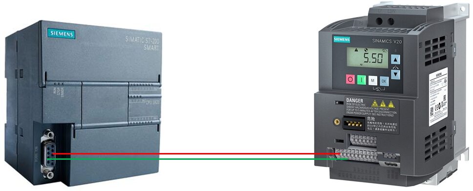
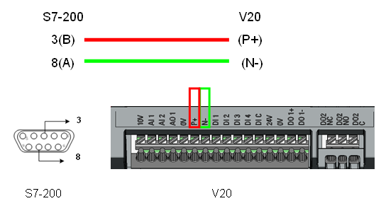
2. Wiring Instructions:
This example is based on the serial port pin description in the operation manual, where pin 3 is the positive RS485 signal and pin 8 is the negative RS485 signal; connect the built-in serial port of S7-200 SMART to the RS485 interface of V20 using a cable (note the port connection rules: V20’s P+ connects to 3, N- connects to 8), as shown in the figure below:
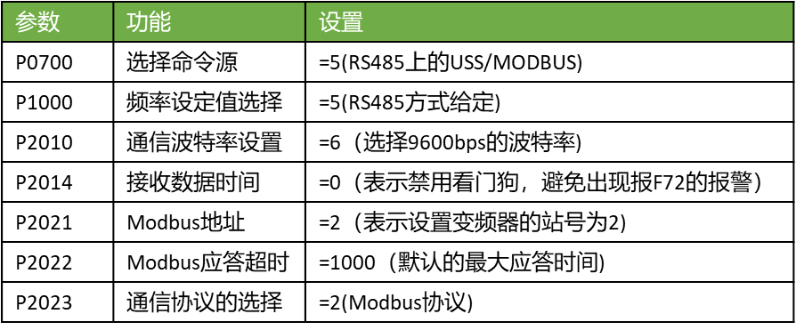
3. Setting Inverter Parameters:
According to the MODBUS communication parameters in the V20 inverter operation manual, the following parameters need to be set for MODBUS communication, as referenced in the figure below. You can refer to the manual for detailed introductions of various parameters. Additionally, you can choose to connect macro CN011. Note: The connection macro must be set while the motor display is active.
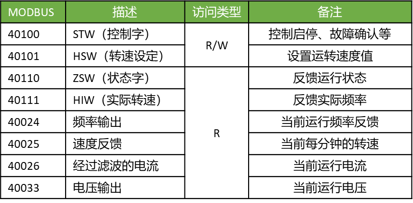
4. Communication Parameter Addresses:
The table below shows some registers supported by the SINAMICS V20 inverter. The “Access Type” column indicates “R” for read, “W” for write, and “R/W” for read/write. HSW (speed set value), HIW (actual speed), STW (control word), ZSW (status word) are control data.
5. Definitions of Control Word Bits:
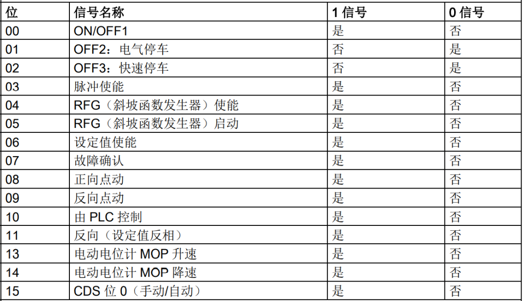
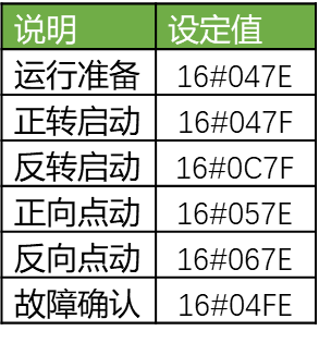
Therefore, the following commonly used control words can be obtained:
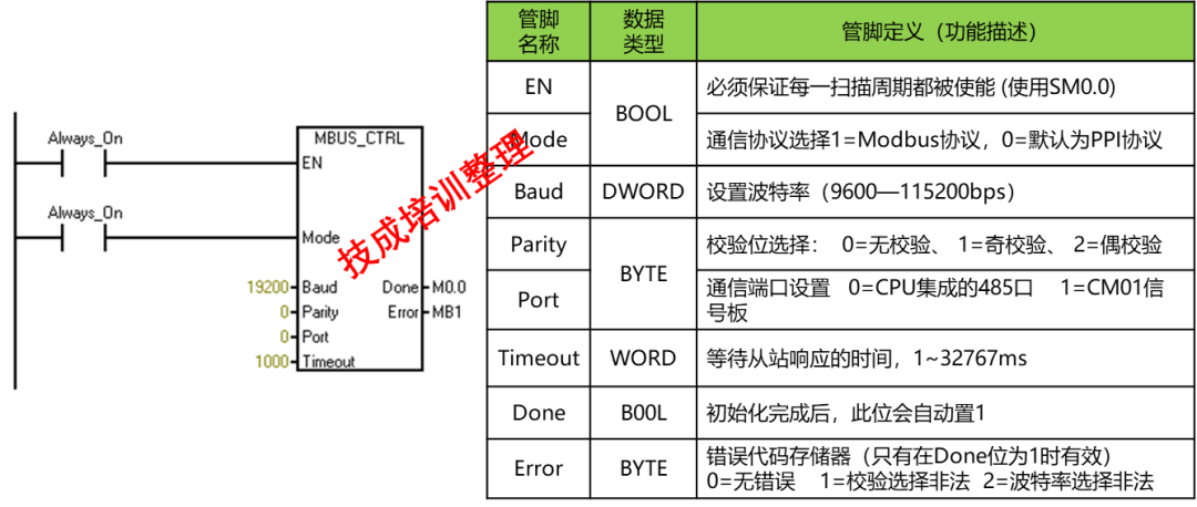
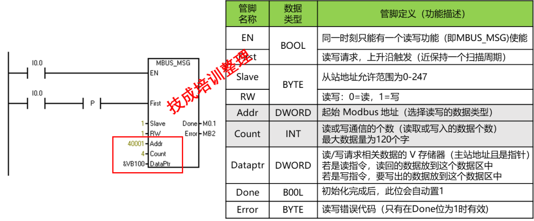
6. Introduction to Communication Instructions:
To achieve the control requirements of this example, the following two communication instructions must be used: one is the communication initialization instruction, and the other is the communication data read/write instruction. The specific instruction introductions are as follows:
7. Program Design:
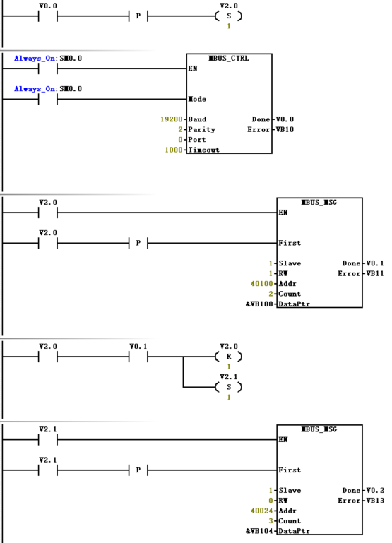
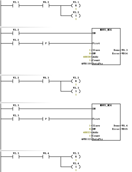
Note: The program is not the complete version.
1. When selecting the connection macro for the Siemens V20 inverter, it is necessary to first restore the default values of the parameters and perform quick debugging before selecting the connection macro;
2. After selecting the corresponding macro, you can also modify one or several parameters individually.
3. When wiring the hardware, be sure to follow the wiring instructions in the manual, especially for the main circuit wiring.
4. If the parameters are set and the program is written but communication fails, it is recommended to check the wiring and all communication parameters, and then use the MODBUS debugging tool to test before finally establishing communication between the PLC and the inverter.
More Content
Please scan the code to view↓

Source: Jicheng Training Network, Author: Jicheng – Sui Xiangjian, unauthorized reproduction is prohibited!