
S7-1200 Modbus RTU Communication Overview
(Data information source: Siemens official website)
Modbus has two serial transmission modes: ASCII and RTU.
Modbus is a master-slave communication mode with a single master station. There can only be one master station on the Modbus network, which does not have an address. Each slave station must have a unique address, with the address range for slaves being 0 – 247, where 0 is the broadcast address and the actual address range for slaves is 1 – 247. Modbus RTU communication transmits data in a master-slave manner, where the Modbus RTU master station is the active party, sending data request messages to the slave station, which returns response messages.
The following S7-1200 modules support Modbus RTU communication:
|
Communication Module/Communication Board |
Order Number |
|
CM1241 RS232 |
6ES7 241-1AH32-0XB0 |
|
CM1241 RS485 |
6ES7 241-1CH30-0XB0 |
|
CM1241 RS422/485 |
6ES7 241-1CH32-0XB0 |
|
CB 1241 RS485 |
6ES7 241-1CH30-1XB0 |
S7-1200 Modbus RTU Instructions
With the continuous updates of TIA PORTAL software and S7-1200 CPU firmware, different versions of S7-1200 Modbus RTU instructions have emerged. Users need to correctly select the S7-1200 Modbus RTU instructions that meet the requirements based on the software and hardware in use to achieve Modbus RTU communication.
Software, hardware requirements, and instruction version descriptions are as follows.

Starting from the STEP 7 V11 version, the instructions “MB_COMM_LOAD” and “MB_MASTER” or “MB_SLAVE” can be directly called from “Instructions” → “Communication Processor” → “MODBUS”, as shown in Figure 1:

Figure 1 Modbus RTU Instructions
Modbus RTU instructions have two versions: V1 and V2. Version V1 was initially provided in STEP 7 Basic V10.5; version V2 was provided in STEP 7 Basic/Professional V11.

The TIA V13 SP1 version software provides two versions of the Modbus RTU instructions. As shown in Figure 2: The earlier version of Modbus RTU instructions (MODBUS (V2.2) in Figure 2) can only be used for Modbus RTU communication via the CM1241 communication module or CB1241 communication board. The new version of Modbus RTU instructions (MODBUS(RTU) V3.0 in Figure 2) extends the functionality of Modbus RTU, supporting not only the CM1241 communication module and CB1241 communication board but also the PTP communication module on PROFINET or PROFIBUS distributed I/O racks for Modbus RTU communication.
Note: Conditions for using the new version of Modbus RTU instructions The new version of Modbus RTU instructions requires the following conditions to be met when communicating via the CM1241 communication module or CB1241 communication board:a. The firmware version of the S7-1200 CPU must not be lower than V4.1;b. CM1241 communication module version 2.1 or higher or CB1241.
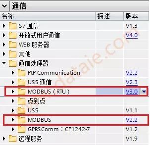
Figure 2. Two Versions of Modbus RTU Instructions

1.Siemens does not provide ready-made instructions for supporting MODBUS-ASCII communication mode; users need to program it themselves using free port mode.

2.Modbus RTU instruction version V2 adds parameters “REQ” and “DONE” to the “MB_COMM_LOAD” instruction. Moreover, the “MB_MASTER” and “MB_SLAVE” instructions now allow a UInt value for the “MB_ADDR” parameter for extended addressing.

3.V1 (V1.x) and V2 (V2.y) instruction versions cannot be used simultaneously in the same CPU program. The Modbus instructions in the user program must have the same major version number; individual instructions within the major version group can have different minor version numbers.

4.For configuring and programming the S7-1200 communication module CM1241, the “MB_COMM_LOAD” instruction can be set to Modbus RTU communication mode. By programming the “MB_MASTER” instruction, the S7-1200 communication module CM1241 can act as the Modbus RTU master station, or by calling the “MB_SLAVE” instruction, it can act as the Modbus RTU slave station.
