1. Introduction to Robots1. Composition of RobotsRobots are composed of mechanical structures driven by servo motors, with each joint or coordinate system at each connection point.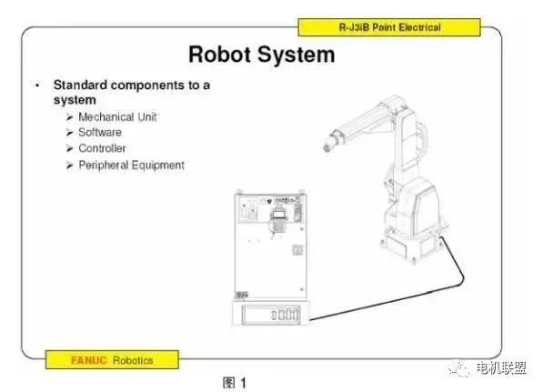 2. Applications of RobotsArc welding, Spot welding, Handling, Sealing, Painting, Deburring, Cutting, Laser welding, Measurement, etc.3. FANUC Robot ModelsMain Models: Model Axis Count Hand Load (kg) LR Mate 100iB/200iB 5/6 5/5 ARC Mate 100iB/M-6iB 6 6/6ARC Mate 120IB/M-16iB 6 16/20 R-2000IA/M-710IAW 6 200/70 S-900IB/M-410IA 6/4 4004. Main Parameters of Robots1) Hand Load2) Number of Motion Axes3) Load on Axes 2 and 34) Motion Range5) Installation Method6) Repeatability Accuracy7) Maximum Motion Speed5. Installation Environment of FANUC Robots1) Ambient Temperature: 0-45 degrees Celsius2) Ambient Humidity: Normal: 75% RH Short-term: 85% (within one month)3) Vibration: =0.5G (4.9M/s2)6. Programming Methods for FANUC Robots1) Online Programming2) Offline Programming7. Special Features of FANUC Robots1) High sensitive collision detector: High-performance collision detection function, no external sensors required, applicable in various situations.2. Composition of FANUC Robots1. FANUC Robot Software System
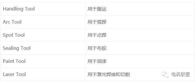 2. FANUC Hardware System1) Basic Parameters: Motor AC servo motor CPU 32-bit high-speed input power R-J3IB 380V/3-phase: R-J3IB Mate 200V/3-phase I/O Devices Process I/O, Module A, B, etc.2) Standalone Form: (See Figure 1)
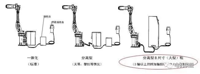 3) Robot System Composition (See Figure 2)
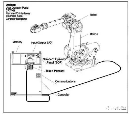 4) Robot Controller Hardware (See Figure 3)
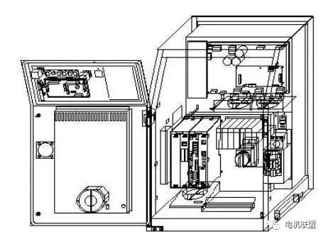 3. Controller1. Understanding TP (Teach Pendant)1) Functions of TP1) Jog the robot2) Write robot programs3) Test run programs4) Production operation5) Check robot status (I/O settings, position, welding current)2) Understanding keys on TP (See image below)
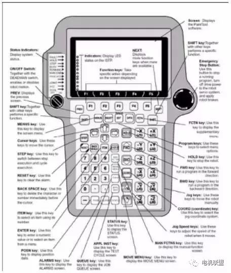 Status Indicators: Indicate system status.ON/OFF Switch: Starts or stops robot movement with the DEADMAN switch.PREV: Displays the previous screen.SHIFT key: Executes specific functions with other keys.MENUS key: Displays the screen menu.Cursor keys: Move the cursor using these keys.STEP key: Switches between single-step execution and loop execution.RESET key: Clears alarms using this key.BACK SPACE key: Clears the character or number before the cursor.ITEM key: Selects the item represented by this key.ENTER key: Inputs values or selects an item from the menu.POSN key: Displays position data using this key.ALARMS key: Displays the alarm screen using this key.QUEUE key: Displays the task queue screen using this key.APPL INST key: Displays the test cycle screen using this key.SATUS key: Displays the status screen using this key.MOVE MENU key: Displays the motion menu screen using this key.MAN FCTNS key: Displays the manual functions screen using this key.Jog Speed keys: Adjust the manual operation speed of the robot using these keys.COORD key: Selects the manual operation coordinate system using this key.Jog keys: Manually operate the robot using these keys.BWD key: Runs the program backward using this key.FWD key: Runs the program forward using this key.HOLD key: Stops the robot using this key.Program keys: Select menu items using these keys.FCTN key: Displays the additional menu using this key. Emergency Stop Button: Stops the running program, turns off the robot servo system’s power supply, and applies brakes to the robot.3) Switches on TP
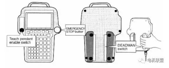 4) Indicators on TP
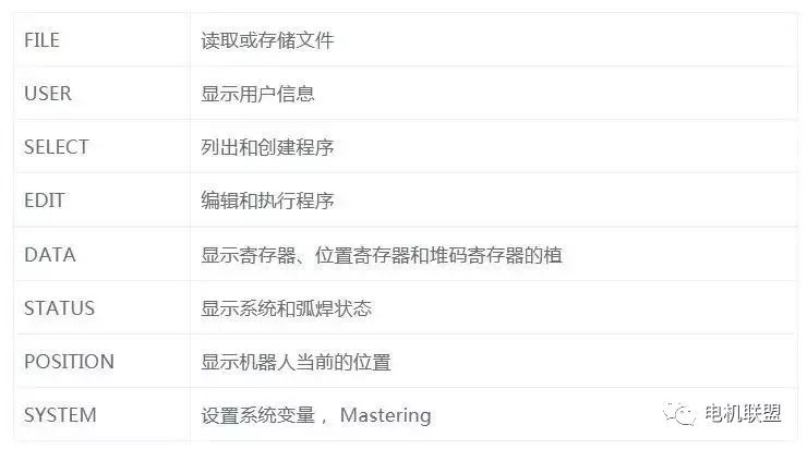
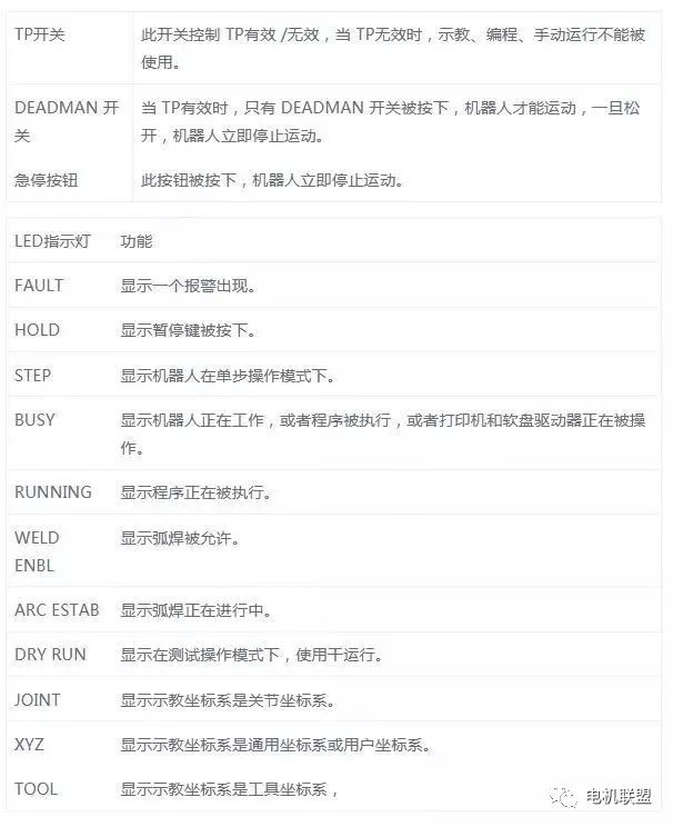 5) Display Screen of TP1) LCD Screen (16*40 lines)2) Displays various TOOL menus (varies)3) Quick/Full menu (selected via FCTN key)Fundamental Knowledge of Robot System Composition, Essential for Robotics Engineers!6) Screen Menu and Function Menu1) Screen Menu
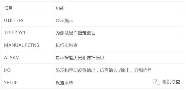
 2) Function Menu (Table 4)
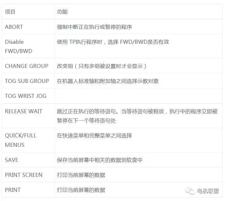 Note: The selection key can display the selection program screen, but other functions cannot be used except for selecting programs. Note: The edit key can display the edit program screen, but other functions cannot be used except for changing the position and speed values.3. Remote Controller The remote controller is a peripheral device connected to the robot controller, used to set up the system, including the following forms:1) User Control Panel2) PLC3) Host Computer4. Monitor and KeyboardThe external monitor and keyboard are connected to the controller via RS-232C and can execute almost all TP functions. Functions related to robot operation can only be implemented through TP.5. Communication1) One standard RS-232C interface (external), two optional RS-232C interfaces (internal)2) One standard RJ45 network interface6. Input/Output I/O Input/Output signals include the following:1) External Input/Output UI/UO2) Operator Panel Input/Output SI/SO3) Robot Input/Output RI/RO4) Digital Input/Output DI/DO (512/512)5) Group Input/Output GI/GO (0 to 32767, up to 16 bits)6) Analog Input/Output AI/AO (0 to 16383, 15-bit digital)Input/Output devices have the following 3 types:1) Model A2) Model B3) Process I/O PC board, among which the Process I/O board can use the most signal lines, up to 512.7. External I/O External signals are used to send and receive signals from remote controllers or peripheral devices, capable of executing the following functions:1) Select programs2) Start and stop programs3) Recover the system from alarm status4) Others8. Robot MotionThe R-J3/R-J3iB controller can control up to 16 axes, with a maximum of 3 groups, each group can control up to 9 axes. The operations of each group are independent of each other. The robot moves based on the teaching or motion instructions in the program. During teaching, the robot’s movement is based on the current coordinate system and teaching speed. When executing the program, the robot’s movement is based on position information, motion mode, speed, termination method, etc.9. Emergency Stop Devices* 2 emergency stop buttons (one on the operation box panel, one on the TP panel)* External emergency stop (input signal) The input terminal for external emergency stop is located in the controller or operation box.1) One standard RS-232C interface (external), two optional RS-232C interfaces (internal)2) One standard RJ45 network interface10. Additional Axes Each group can have up to 3 additional axes (in addition to the robot’s 6 axes). Additional axes have the following 2 types:1) External axes that are controlled independently of the robot’s motion and can only move at joints.2) Internal axes that are controlled together with the robot during linear or circular motion.
If there are copyright issues or if you do not wish to reprint, please contact this public account.
Source: Qianxun Life