The development of hard disk technology has gone through multiple advancements and transformations in interface technology. Storage expert Wu will lead everyone to explore the grand view of hard disk interfaces and witness the past and future of hard disk interfaces.
Old Disk Interfaces
IDE Interface
IDE (Integrated Drive Electronics) is a disk interface that was widely used in personal computers. It uses parallel data transmission, and the interface is relatively large, as shown in the figure below:
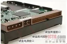
The IDE bus is a shared bus, and to increase the number of devices on an IDE bus, each IDE bus can support two devices, namely a master device and a slave device. The connection cable between the host and the IDE device is shown in the figure below, where the blue connector connects to the host; the white connector is the slave device interface; and the black connector is the master device interface.

There are two data transmission modes for the IDE interface: one is PIO (Programming Input/Output); the other is DMA mode. In the era when data transmission volume was not very large, DMA, which required continuous configuration of the DMA controller, was less efficient than PIO. However, driven by the demand for high-performance data transmission, DMA finally demonstrated its expected performance. Initially, the DMA data transmission mode of IDE used a simple single multiplier working mode, meaning that within one clock cycle, only one bus data transmission operation occurred. Later, the IDE bus introduced UDMA (Ultra DMA) data transmission mode, where both the rising and falling edges of one clock cycle conduct data transmission operations, thereby doubling the transmission efficiency. This data transmission mode is also known as double-edge data transmission, similar to DDR in memory.
Above the IDE interface runs the ATA disk control protocol, so this interface is also commonly referred to as PATA (Parallel ATA). PATA has various interface standards from ATA1 to ATA7, catering to different access performance and characteristics. Among them, ATA7 achieves a bandwidth of nearly 133MB/s. Due to interference between parallel signal transmissions, the sampling of parallel signals can exhibit significant phase errors, leading to severe bottlenecks in improving the performance of the IDE interface. Therefore, currently no hard disks use this old IDE interface, which has all been replaced by serial ATA interface technology.
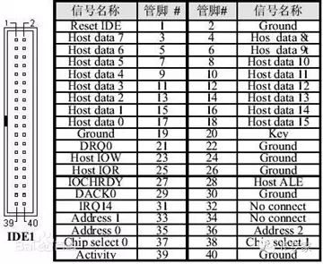
The IDE uses a 40-pin interface format, and the interface signal definitions are as follows:
In the early 2000s, I assembled my first computer using the largest 30GB Maxtor hard drive at the time, which used this IDE interface. During assembly, the hard drive was set as the master device and the optical drive as the slave device. Currently, IDE can no longer support hard disk data transmission needs and has been phased out. However, the ATA protocol (command set) developed on IDE has been inherited by SATA and continues to be used.
SCSI Interface
SCSI (Small Computer System Interface) is an interface for connecting hosts and peripheral devices. The hard drive using the SCSI interface is shown in the figure below:
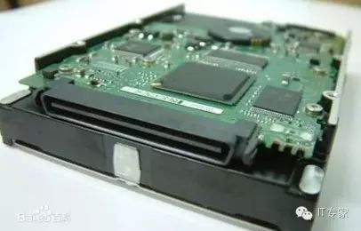
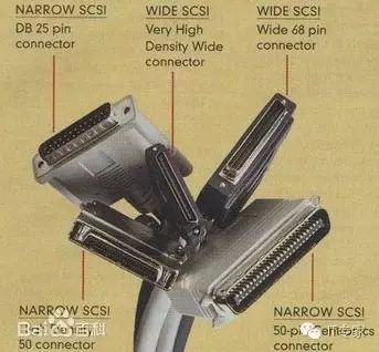
Compared to IDE, the SCSI interface has better transmission performance and is usually used in server hard drives. Hard drives using this interface offer better stability and faster performance, but they are also significantly more expensive than IDE hard drives. There are many types of SCSI connectors and specifications, with several common connector types shown in the figure below:
The most critical difference between SCSI and IDE hard drives is not in the interface. As enterprise-level application disks, they need to have high data access performance, which is why SCSI hard drives have higher rotational speeds. Once the rotational speed increases, the temperature of the disk also rises, and the difficulty of seeking and positioning increases. Therefore, enterprise-level disks like SCSI differ significantly from ordinary hard drives in aspects such as disk materials, disk control, and data error correction, leading to higher stability and performance.
The physical bus interface of SCSI hard drives is no longer in use, but the application layer protocols developed on SCSI bus technology (SCSI command set) are still retained and have been inherited by SAS interconnect networks.
FC Interface
FC hard drives refer to disks that use the FC-AL (Fiber Channel Arbitrated Loop) interface mode. This interface uses a 40-pin signal definition. The serial hard disk interface is shown in the figure below:
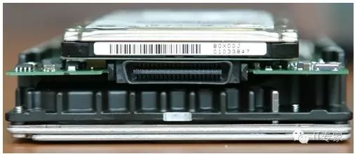
FC hard drives use the FC-AL bus protocol. In practical applications, all hard drives are connected in series to form an arbitration loop, as shown in the figure below:
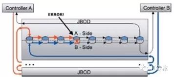
This connection method can expand capacity, but it also has a significant drawback: if there is a faulty connection in one loop, the access of the entire link will be affected. In EMC’s high-end storage Vmax products, FC disks were used until 2014 when the Vmax3 was released, which replaced these FC disks with SAS disks. After adopting SAS disks, all SAS or SATA disks can form a backend disk storage network through the SAS Expander, as shown in the figure below:
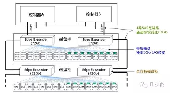
In high-end storage systems, FC disks were widely used in the backend storage network to improve disk performance and expand storage capacity. However, with the continuous advancement and development of SAS technology, SAS networks ultimately replaced FC networks in the backend.
Serial ATA Interface
Which is faster, parallel or serial data transmission? When asked this question, one subconsciously thinks that parallel transmission has higher performance. In one clock cycle, parallel transmission can send multiple bytes; however, serial communication can transmit at most two bits in one clock. But due to signal interference and data sampling issues during parallel data transmission, parallel transmission cannot increase clock frequency. In contrast, low-voltage differential serial transmission does not have sampling phase difference issues, allowing for very high clock frequencies during data transmission, thus making serial transmission performance far superior to parallel transmission. The development of serial data transmission solved the problems present in parallel buses. After 2000, not only did ATA develop in the serial direction, but SCSI and PCI also faced the same issues. Therefore, SATA was developed based on ATA; SAS was developed based on SCSI; and PCI Express was born based on PCI.
SATA Interface
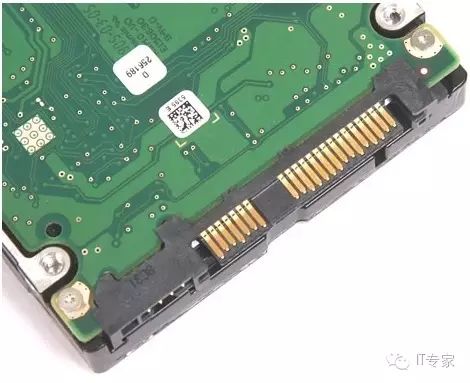
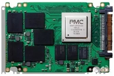
SATA interface hard drives are commonly used in consumer-grade and civilian ordinary hard drives. The hard drive using the SATA interface is shown in the figure below:
SATA stands for serial ATA. It uses serial data transmission to achieve high-speed disk access interfaces. To date, SATA has formed three standards: SATA1 can achieve 1.5Gbps transmission performance; SATA2 can achieve 3Gbps; and SATA3 reaches a communication speed of 6Gbps. The data transmission efficiency of the SATA interface is far higher than the performance of the disk itself, hence the performance of the disk is limited by the mechanical seek overhead of the disk itself. The SATA interface is shown in the figure below:
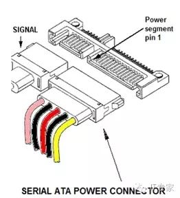
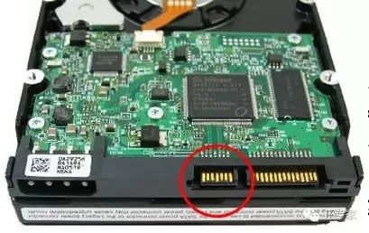
The SATA interface is mainly divided into two major parts: the signal area and the power area, and the signal area and power area are separated from each other. It is particularly important to note the gap (notch) between these two areas, which is the distinguishing mark between SATA and SAS. The SATA interface on an ordinary motherboard is shown in the figure below:
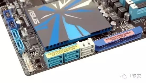
Currently, consumer hard drives basically all use SATA interfaces, including disks and SSDs. Since SSDs use NAND Flash technology, which belongs to semiconductor storage, there are no mechanical addressing issues, significantly improving storage access performance, resulting in the SATA interface itself becoming a performance bottleneck for storage disks.
As of today, the highest communication speed of the SATA standard can reach 6Gbps, which is half the performance of SAS interfaces. The SATA interface uses a mode with seven signal lines, specifically defined as follows:
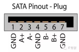
1, GND ground signal
2, A+ data sending differential signal
3, A- data sending differential signal
4, GND ground signal
5, B- data receiving differential signal
6, B+ data receiving differential signal
7, GND ground signal
From the definitions above, it can be seen that the SATA interface employs a pair of differential signal lines for full-duplex data transmission. Compared to the SAS interface, it does not provide dual-port functionality. In enterprise applications, dual-port functionality support is typically required, so a port conversion board is needed to convert one port of SATA into two ports. These two ports switch between each other through an analog switch.
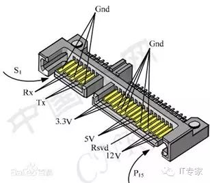
The power part of the SATA interface provides 3.3V, 5V, and 12V. The specific definitions are as follows:
The SATA interface is a milestone in the development of hard disk interface technology, providing very high-speed performance and seamlessly integrating into the SAS architecture. Therefore, both in consumer applications and enterprise applications, SATA hard disks have an irreplaceable position. However, with the rapid development of SSD technology, the SATA interface has again encountered performance issues, and the new NVMe standard continuously impacts SATA.
mSATA Interface
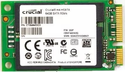
In systems like laptops where size is a concern, DOM disks are often used, and these disks utilize the more compact mSATA interface. mSATA is a mini version of standard SATA, widely used in laptops and some server systems.
It is important to note that the appearance of the mSATA interface is identical to that of mini PCI-E, but in terms of signal definitions, the two interfaces are completely different. mSATA needs to connect to the SATA controller; mini PCI-E needs to connect to the PCIe bridge. If the same interface needs to support both mSATA and mini PCI-E simultaneously, a bidirectional multiplexer needs to be introduced at this interface. In the mSATA interface, the 43-pin is grounded; mini PCI-E is floating, allowing for automatic selection of the interface through this pin. A bidirectional multiplexer can be implemented using NXP’s CBTL02042 chip.
The solid-state disk using the mSATA interface is shown in the figure below:
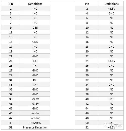
The signal definitions for the mSATA interface are as follows:
Compared to the SATA interface, mSATA reduces the size. However, compared to the developing M.2 interface, it still appears large, and mSATA cannot support the developing PCIe hard disk interface technology. In future trends, the M.2 interface will replace the mSATA interface.
SATA Express
Due to the PCIe bus being closer to the CPU, storage disks based on the PCIe interface have higher data throughput and lower latency; therefore, more and more SSDs are using PCIe as their data transmission interface. SATA Express was born against this need, aiming to further compatibility with PCIe data transmission modes based on the SATA interface. SATA Express is a multiplexing interface between SATA and PCIe, allowing the same interface to support both PCIe and SATA physical interfaces. The interface definition for SATA Express is shown in the figure below:
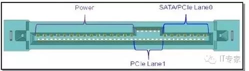
The SATAe interface uses PCIe pathways for data transmission, improving transmission performance. In the SATAe standard, the native SATA interface can be accessed directly through AHCI; or data can be transmitted through the PCIe interface using the NVMHCI interface. The SATAe interface only supports SATA and PCIe, so it is a transitional standard that will be replaced by the SFF-8639 interface in the future. Currently, Intel has abandoned support for the SATA Express interface.
Serial SCSI Interface
Similar to the development of SATA, due to the performance issues of parallel SCSI, the SAS interface technology was created. As in the SCSI era, the SATA interface primarily serves the consumer market; the SAS interface is mainly used in the enterprise market. Compared to the SATA interface, the SAS protocol system is much more extensive. SAS is not only a device interconnect bus but, more importantly, SAS technology builds backend storage networks. Through SAS networks, a certain number of storage disks can be interconnected to form backend storage networks.
SAS Interface
The enterprise-level disk using the SAS interface is shown in the figure below:
Visually, SAS and SATA interfaces are very similar; the difference lies in whether there is a notch in the middle. For SATA interfaces, the signal area and power area are separated, with a notch in the middle. In contrast, the SAS interface has no notch in the middle and adds a set of transmission signals as shown in the figure below:
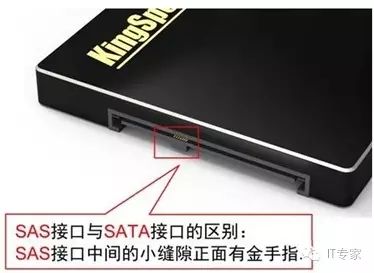
This newly added signal group is used to implement the dual-port functionality of SAS. As an interface for enterprise applications, dual-port functionality is required to support multipath applications.
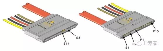
The signal definitions for the SAS disk-side connectors are as follows:
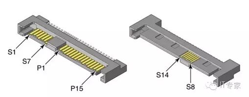
Where S1~S7 are the first SAS port; S8~S14 are the second SAS port. P1~P15 are the power lines. Compared to SATA, S8~S14 signal lines are added. The SATA disk-side interface is also known as the male connector, while the backplane-side interface is referred to as the female connector.
The signal definitions for the SAS backplane connectors are as follows:
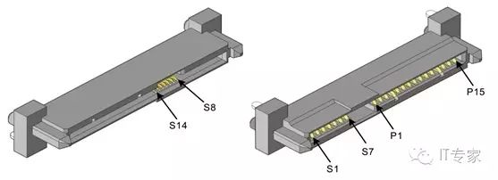
The signal functions are entirely the same as those of the disk-side signal definitions. Since the SATA disk has a gap in the middle, SATA can be correctly connected to the SAS backplane connector. In other words, SAS can be compatible with SATA. Therefore, in current mainstream storage systems, SAS backplanes and SAS Expanders are commonly used, with SATA hard disks utilized in such SAS networks. This approach to storage systems is primarily based on the consideration that SATA disks are cost-effective, and their capacity far exceeds that of SAS disks.
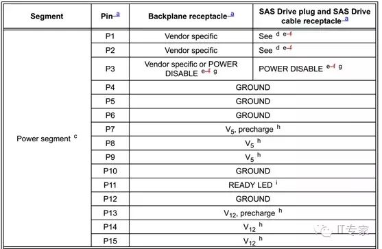
The signal definitions for the SAS disk connectors and backplane connectors are as follows:
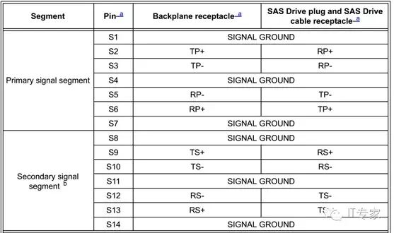
SAS uses a dual-port, full-duplex operating mode. Therefore, both sending and receiving signals have two pairs of differential signal pairs. The power signal definitions for the SAS connectors are as follows:
SAS Internal Connection Cables
One feature of the SAS interface is the wide variety of connection cable standards, which are primarily divided into internal connection cables and external connection cables. One commonly used internal connection cable for connecting hard disks is shown in the figure below:
This type of cable carries both power and signal lines and can connect directly to the hard disk. When the hard disk backplane needs to connect to an export adapter card, the following type of connection cable can be used:
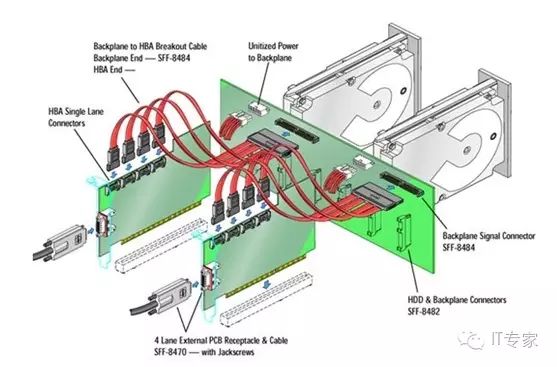
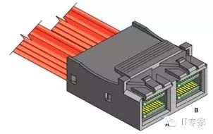
The connection cable defined in the figure above occupies a large volume; thus, the SAS standard defines Mini-SAS cables and connectors. The internal Mini-SAS interface is used for internal SAS interconnection, and one Mini-SAS interface can support four PHYs. The internal Mini-SAS cable connector standard complies with SFF-8087 and SFF-8086. The specific interface definitions are shown in the figure below:
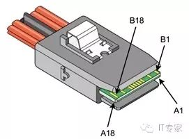
The board-end connector is shown in the figure below:
The signal definitions for the internal Mini-SAS connectors are as follows, supporting multiple PHYs, with a maximum of four PHY interconnections.
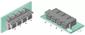
The internal Mini-SAS HD interface is smaller than the Mini-SAS interface. Mini-SAS HD is referred to as high-density Mini-SAS. The following figure shows the Mini-SAS HD interface (Mini-SAS HD 4i) that supports four PHYs:
The Mini-SAS HD socket is shown below:
The Mini-SAS HD interface (Mini-SAS HD 8i) that supports eight PHYs integrates the above Mini-SAS HD interfaces, as shown in the figure below:
The socket for Mini-SAS 8i is shown below:
SAS External Interconnect Cables
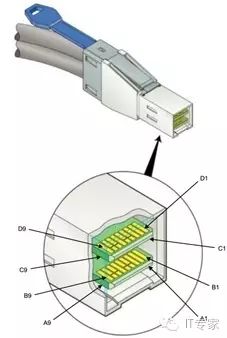
Since SAS can build a storage network, external interconnect cables need to be defined. External interconnect cables differ from internal cables, providing better connection reliability and usability. External cables also have mini-SAS and mini-SAS HD distinctions, with the interface definition for mini-SAS external cables shown below:
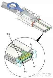
The socket for Mini-SAS external cables is shown in the figure below:
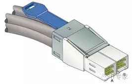
The Mini-SAS interface is relatively large; thus, to reduce its size, SAS defines high-density mini-SAS interfaces. The external interconnect cable for Mini-SAS HD is shown below:
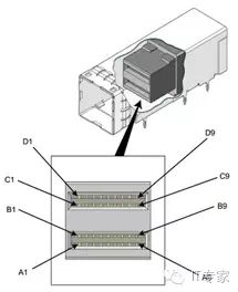
The above Mini-SAS HD interface can support four PHY interconnections. The Mini-SAS HD (mini-SAS 8i) shown below can support eight PHY interconnections:
The socket for Mini-SAS 8i is shown below:
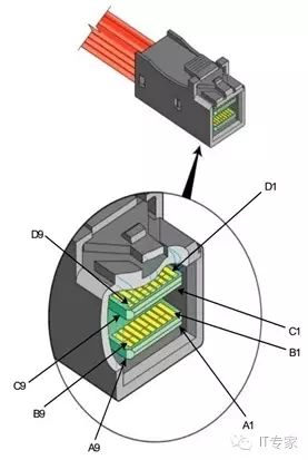
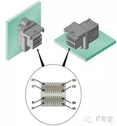
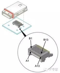
In addition to using mini-SAS/mini-SAS HD for interconnection, SAS can also use QSFP connectors, which can support four PHY interconnections:
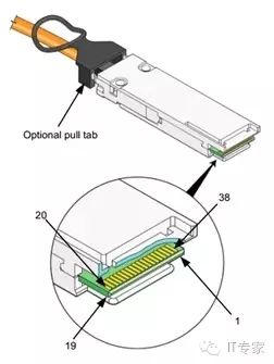
The appearance of the QSFP socket is shown in the figure below:
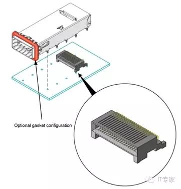
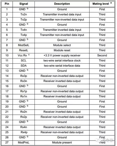
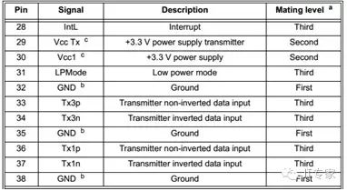
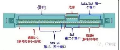
The signal definitions for the QSFP connector are as follows:
SAS technology is still under development. With the advancement of SSD technology, SAS faces challenges from PCIe interface technology. However, since PCIe interface technology is not designed as an interconnect technology for storage, many issues still exist in the storage field, especially in backend storage interconnections. Therefore, it is believed that NVMe disks will eventually replace SAS high-performance disks, but SAS interconnect technology will continue to exist and develop for a considerable time.
NVMe SSD Interface
With the development of SSD storage technology, traditional SAS and SATA interfaces have encountered significant bottlenecks. Therefore, high-performance SSDs use PCIe data transmission interfaces. To standardize this interface, various interface standards have been proposed in the industry, with the mainstream interface standards being SFF-8639 and M.2.
SFF-8639
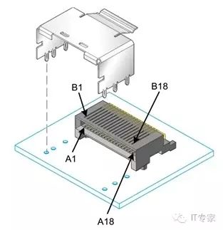
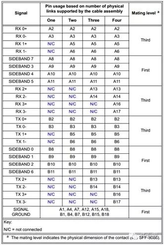
The SFF-8639 interface is also known as the U.2 interface. This interface is developed based on the SAS interface, allowing compatibility with SATA, SAS, and PCIe. The interface definition for SFF-8639 is shown in the figure below:
As shown in the figure, the red area indicates PCIe signals; the blue area indicates SAS/SATA signals. This interface can support multi-port SAS and up to four lanes of PCIe bus. Currently, this interface is commonly used in NVMe SSDs, and the interface method is consistent with SATA and SAS disks:
Since 2014, many manufacturers have launched NVMe SSDs based on the SFF-8639 interface, and more server manufacturers have made this interface a standard configuration for servers. It can be said that SFF-8639 is bound to have a brilliant future.
M.2 Interface
For ultra-thin devices like ultrabooks, extreme compactness is required. The M.2 interface is smaller than mSATA. The M.2 interface standard was released in 2012 and can support various modules on the same connector, including:
1, WiFi
2, Bluetooth
3, Global Positioning System
4, NFC
5, SSD
6, Wireless Wide Area Network
The host interfaces that this interface can cover include:
1, PCIe
2, USB
3, UART
4, SATA
5, Display Port
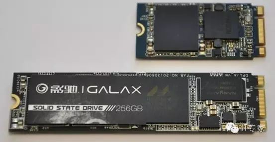
The M.2 interface is an upgraded version of the Mini PCIe/mSATA interface. M.2 SSDs are divided into SATA and PCIe interface methods, classified into Socket 2 and Socket 3 types. Socket 2 supports SATA and PCIe X2 interfaces, while Socket 3 can support PCIe X4 interfaces. The SSDs for laptops based on the M.2 interface are shown in the figure below:
 Focus on IT, focus on innovation, for more information and the latest updates, please follow this WeChat account!
Scan the QR code to follow this public account