This article will detail the steps for connecting the Siemens S7-200 SMART PLC with the Smart Line touch screen via Modbus RTU communication.


As shown in Figure 1:
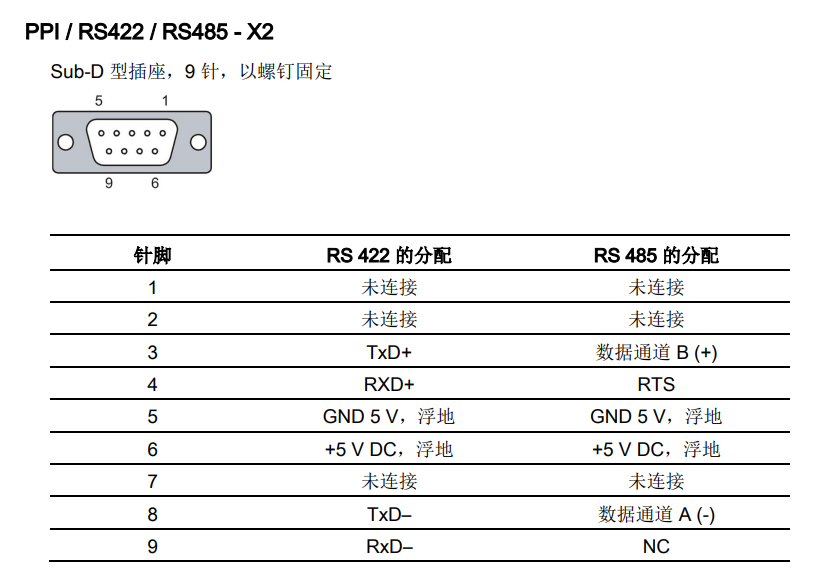 Figure 1
1) 200 SMART PLC body port
The 200 SMART PLC can choose the CPU-integrated RS485 communication port and the standard CPU additionally supports the SB CM01 signal board. The pin assignment of the CPU integrated RS485 communication port is shown in Figure 2, and the CPU additionally supports the SB CM01 signal board.
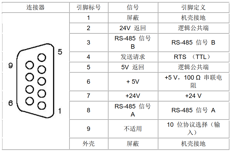
Figure 2
2) 200 SMART signal board
The standard CPU additionally supports the SB CM01 signal board, which can be configured as the RS485 communication port or RS232 communication port through STEP 7-Micro/WIN SMART software. The pin assignment of the SB CM01 signal board is shown in Figure 3.
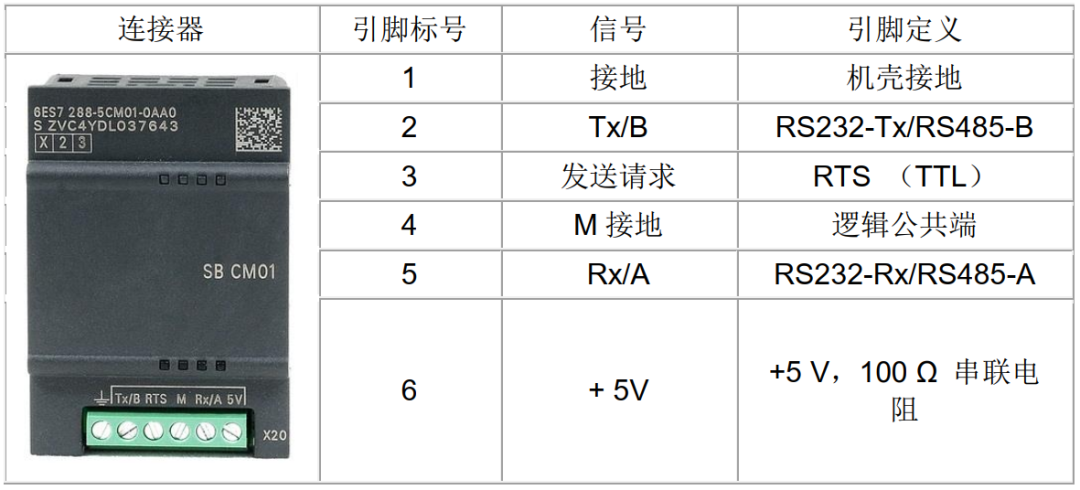
Figure 3
1) CPU integrated RS485 communication port connected to the touch screen
PLC port pin 3 connects to touch screen port pin 3, PLC port pin 8 connects to touch screen port pin 8, as shown in Figure 4.
2) SB CM01 signal board connected to the touch screen
SB CM01 signal board Tx/B connects to touch screen RS-485 port pin 3, SB CM01 signal board Rx/A connects to touch screen RS-485 port pin 8,
as shown in Figure 4,this article discusses communication connections for the 200 SMART PLC body port.
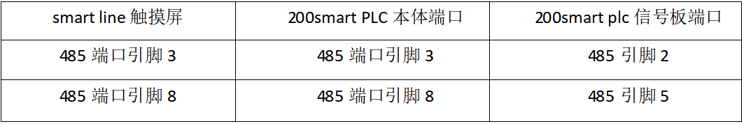
Figure 4


1) Open WinCC flexible SMART software, create a new project in the file menu and select the Smart 700 IE V3 touch screen, as shown in Figure 5;
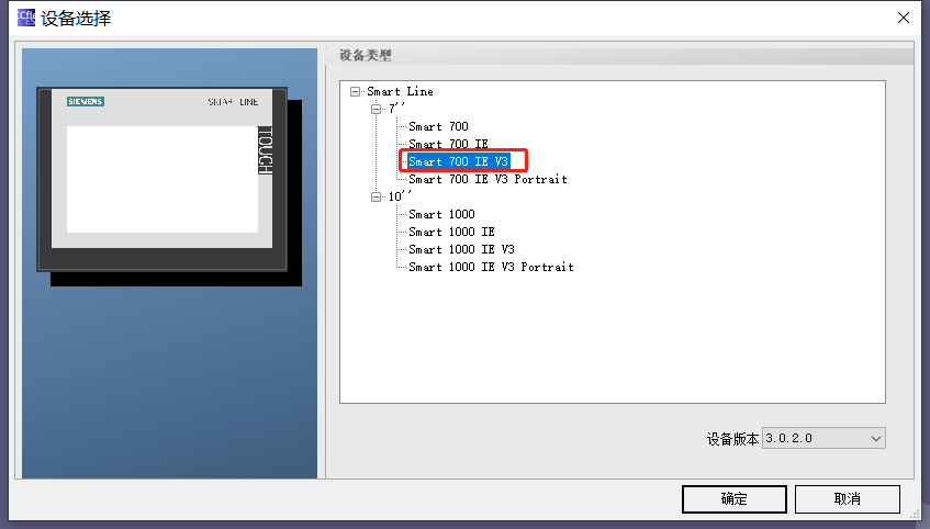 Figure 5
2) In the project bar under Communication – Connection, set communication parameters; Modbus RTU communication can have three options, as shown in Figure 6.
When connecting the 200 SMART PLC with the smart line touch screen, be sure to check “Change word order”.
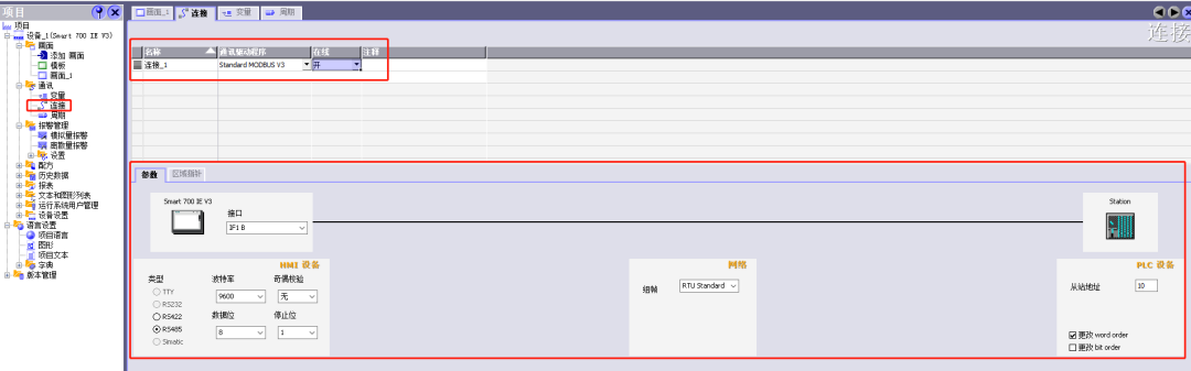
Figure 6
3) Variable Creation
Create PLC connection variables, as shown in Figure 7:
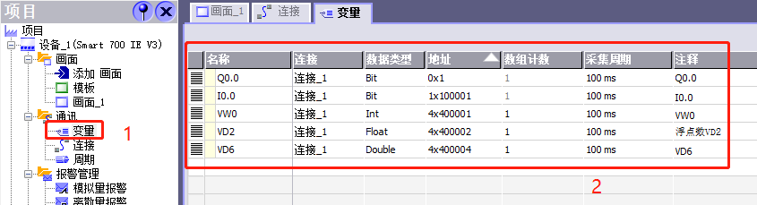
Figure 7
The MODBUS RTU addresses for the 200 SMART PLC are as follows:
u For discrete output (coils), from 00001 to 09999
u For discrete input (contacts), from 10001 to 19999
u For input registers, from 30001 to 39999
u For holding registers, from 40001 to 49999 and 400001 to 465535
The holding registers for the 200 SMART programming slave start from VW0 (related to program programming, the subsequent programming section will introduce this), so 400001 corresponds to VW0.
Use the toolbar to select circles, text fields, and IO fields to edit the configuration, as shown in Figure 8, and follow the configuration steps to create the program.
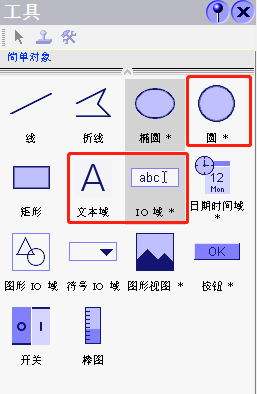
Figure 8
1) Indicator Light Configuration
The configuration is shown in Figure 9:
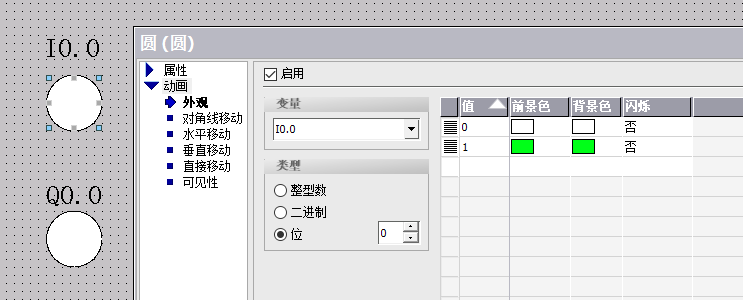
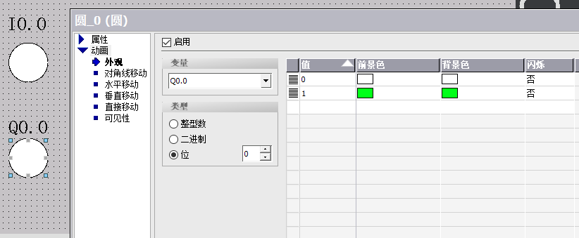
Figure 9
2) 16-bit Unsigned Integer Configuration
The configuration is shown in Figure 10:
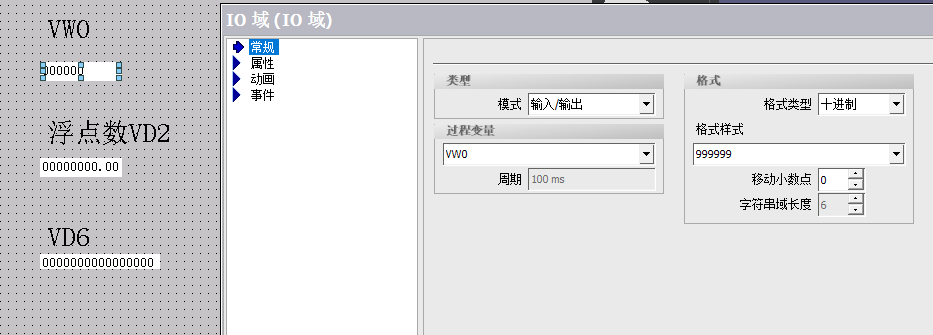
Figure 10
3) 32-bit Unsigned Integer Configuration
The configuration is shown in Figure 11:
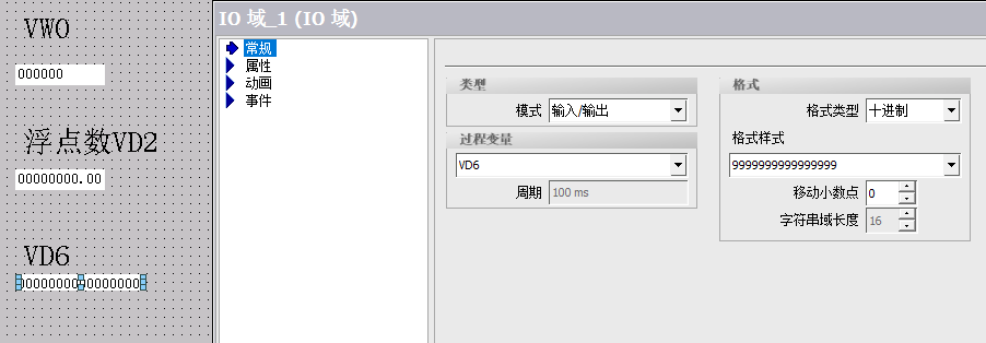
Figure 11
4) 32-bit Floating Point
The configuration is shown in Figure 12:
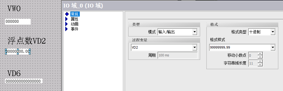
Figure 12
Refer to the attachment “Common Problems in Smart V3 Panel” for project download, as shown in Figure 13.
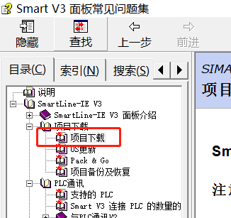
Figure 13


Open the STEP 7-MicroWIN SMART software, find the Modbus RTU slave library, and then write the Modbus RTU slave program, as shown in Figure 14. It is important to allocate addresses to the library storage area, right-click on the library in the program block to select storage area allocation, as shown in Figure 15. After writing the program, download it to the PLC, and switch the PLC to run mode.
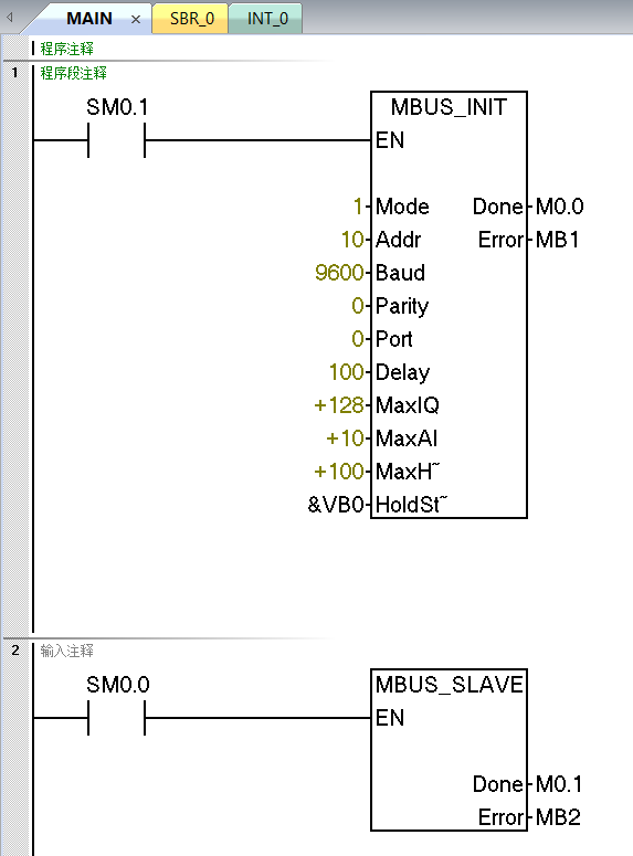
Figure 14
The value input for the “Mode” selects the communication protocol: when the input value is 1, the Modbus protocol is assigned and enabled; when the input value is 0, the PPI protocol is assigned and the Modbus protocol is disabled.
The parameter “Address” sets the address to a value between 1 and 247 (inclusive).
The parameter “Baud” sets the baud rate to 1200, 2400, 4800, 9600, 19200, 38400, 57600, or 115200.
The parameter “Parity” should be set to match the parity check of the Modbus master. All settings use one stop bit. The accepted values are: 0 (no parity), 1 (odd parity), and 2 (even parity).
The parameter “Port” sets the physical communication port (0 = integrated RS-485 in CPU, 1 = RS-485 or RS-232 on optional signal board).
The parameter “Delay” increases the timeout condition for standard Modbus information by the allocated number of milliseconds. When running on a wired network, a typical value for this parameter should be 0. If using a modem with error correction, set the delay to a value between 50 and 100 ms. If using spread-spectrum wireless communication, set the delay to a value between 10 and 100 ms. The “Delay” value can be between 0 and 32767 ms.
The parameter MaxIQ sets the number of I and Q points available for Modbus addresses 0xxxx and 1xxxx, with a range of 0 to 256. A value of 0 disables all read and write operations for inputs and outputs. It is recommended to set the MaxIQ value to 256.
The parameter MaxAI sets the number of word input (AI) registers available for Modbus address 3xxxx, with a range of 0 to 56. A value of 0 prohibits reading analog inputs. It is recommended to set MaxAI to the following values to allow access to all CPU analog inputs:
u 0 (for CPU CR20s, CR30s, CR40s, and CR60s)
u 56 (for all other CPU models)
The parameter MaxHold sets the number of word holding registers in the V memory accessible for Modbus addresses 4xxxx or 4yyyyy. For example, if you want to allow the Modbus master to access 2000 bytes of V memory, set the MaxHold value to 1000 words (holding registers).
The parameter HoldStart is the starting address of the holding registers in V memory. This value is usually set to VB0, so the HoldStart parameter is set to &VB0 (address VB0). Other V memory addresses can also be specified as the starting address for holding registers to be used elsewhere in the project. The Modbus master can access V memory with a starting address of HoldStart and a number of words equal to MaxHold.
The output “Done” is activated when the MBUS_INIT instruction is completed.
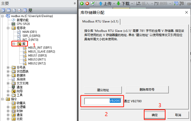
Figure 15


As shown in Figure 16, the touch screen and PLC have successfully communicated, and data exchange has been realized; Figure 17 shows the data from the 200 SMART PLC slave.
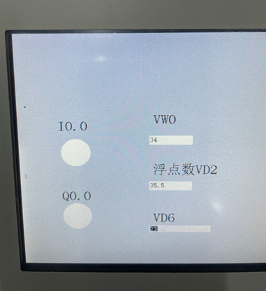
Figure 16
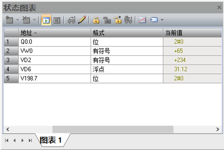
Figure 17
Above are the steps for connecting the Siemens S7-200 SMART PLC with the Smart Line touch screen via Modbus RTU communication. If there are any errors in the content of the article, please contact us.
(Original content from Technical Training Network, Author: Zou Zhirui, unauthorized reproduction is prohibited, violators will be prosecuted)
1. Software Description
1) 200 SMART programming software
STEP 7-Micro/WIN SMART v2.5 or above
2) Smart line touch screen configuration software
WinCC flexible SMART V3 sp2 or above
2. PLC Program, scan to receive
3. Touch Screen Program, scan to receive

4. Common Problems in Smart V3 Panel, scan to receive

Note: The above files can be scanned using the QR code below, the path is: [Essential for Electrical Practitioners] – [Official Account Article Source Program]