In serial communication, both parties are required to use a standard interface, allowing different devices to connect easily for communication. The RS-232 communication standard is defined by a 25-pin interface and was widely used in early computers such as PC or XT models. However, in models after the AT series, a simplified 9-pin version is commonly used, and the term RS-232 communication generally refers to the 9-pin interface. Currently, RS-232 is the most widely used serial interface in PCs and the communication industry. Examples related to serial ports include:STM32 printing data to the serial assistant. RS-232 is defined as a single-ended standard that increases communication distance in low-speed serial communication. RS-232 uses an unbalanced transmission method, known as single-ended communication.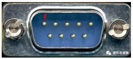 The RS232 (9-pin) interface is explained by the following pin numbers: 1 Carrier Detect (DCD) 2 Receive Data (RXD) 3 Transmit Data (TXD) 4 Data Terminal Ready (DTR) 5 Signal Ground (SG) 6 Data Set Ready (DSR) 7 Request to Send (RTS) 8 Clear to Send (CTS) 9 Ring Indicator (RI) DB9 Male (Pin Side) DB9 Female (Pin Side) DB9 Female (Solder Side) DB9 Male (Solder Side)
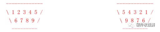 From the two diagrams, it can be seen that when the male and female connectors are connected, RXD-RXD and TXD-TXD are linked. Therefore, it can be inferred that the two ends of the download cable should connect RXD-RXD and TXD-TXD. However, when purchasing a serial cable, a crossover serial cable is needed (to achieve RXD-TXD connection), thus enabling one end to send and the other to receive.
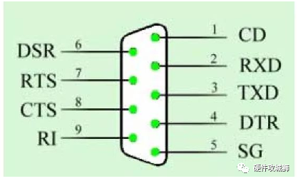 Nowadays, most computers are equipped with this standard 232 interface, which is typically used to connect external devices such as mice, modems, or printers. In practical applications, electronic engineers often simplify the communication design between computers and peripheral devices based on the 9-pin interface, using only pins 2, 3, and 5 for communication. These three pins correspond to the receive line, transmit line, and ground line, which generally meet the communication requirements.
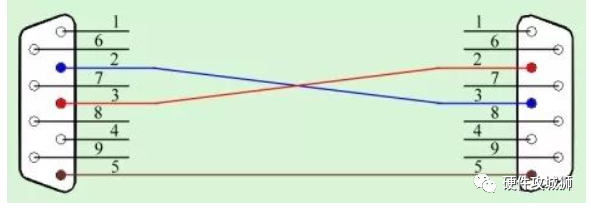 It is worth noting that in the above diagram, pins 2 and 3 are cross-connected, which is easy to understand because one device’s transmit line must connect to the other device’s receive line, and vice versa.
Statement: The article is sourced from the internet, and the copyright belongs to the original author. If there is any infringement, please contact us for removal!

「If useful, please share」
❤❤❤
Click follow; for timely delivery of electronic materials!
👇

-
Capacitor Selection and Formula Compilation
-
Three commonly used open-source libraries that make microcontroller development more efficient!
-
What is the purpose of adding a small resistor in the signal line?
-
After reviewing these common operational amplifier circuit calculations and analyses, I gained insight
-
These free circuit design software tools will definitely be useful to you!
-
After reviewing these common operational amplifier circuit calculations and analyses, I gained insight
-
After reading this, you will also be a PID tuning expert!
Please like and share if you enjoy it; good articles need your support and encouragement