Serial communication is the most basic communication method that electrical engineers face, with RS-232 being the simplest of them. Many beginners often get confused about the relationship and differences between UART and RS-232, RS-422, and RS-485. This article will discuss the understanding of these concepts to help clarify their relationships.
If we compare serial communication to traffic, UART can be likened to a station, while a frame of data is like a car. Cars on the road must obey traffic rules. In urban areas, the speed limit is generally 30 or 40, while on highways it can go up to 120. The speed limit and the type of road depend on the protocol specifications. Common serial port protocols include RS-232, RS-422, RS-485, etc. What are the subtle differences between them? Let’s explore.
1. What is UART
UART stands for Universal Asynchronous Receiver/Transmitter, and it is a key module for asynchronous communication between devices. UART is responsible for converting between serial and parallel data on the data bus and serial port, and it specifies the frame format. As long as both communicating parties adopt the same frame format and baud rate, communication can be completed using just two signal lines (Rx and Tx) without sharing a clock signal, hence it is also referred to as asynchronous serial communication.
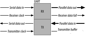
With a suitable level converter, such as SP3232E or SP3485, UART can also be used for RS-232 or RS-485 communication, or connected to a computer port. UART is widely used in applications such as mobile phones, industrial control, and PCs.
UART uses asynchronous serial communication.
Serial communication refers to the sequential transmission of data bit by bit over a single transmission line. The characteristics include simple communication lines, which can be achieved using simple cables, reducing costs, and it is suitable for long-distance communication but with slower transmission speeds.
Asynchronous communication uses a character as the transmission unit, and the time interval between two characters during communication is not fixed. However, the time interval between two adjacent bits in the same character is fixed.
The data transmission rate is expressed in baud rate, which indicates the number of binary bits transmitted per second. For example, if the data transmission rate is 120 characters per second, and each character consists of 10 bits (1 start bit, 7 data bits, 1 parity bit, 1 stop bit), then the baud rate is 10×120=1200 characters/second=1200 baud.
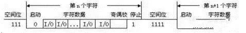
The data communication format is shown in the figure below:
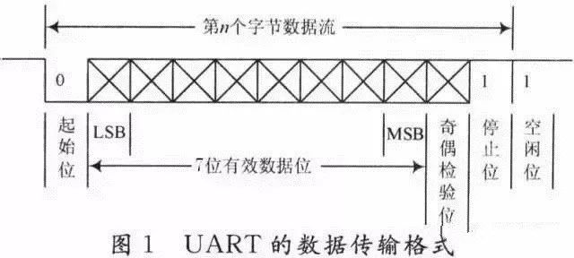
The meanings of each bit are as follows:
Start Bit: A logical “0” signal is sent first to indicate the start of the transmission character. Data Bits: Can be 5 to 8 bits of logical “0” or “1”. For example, ASCII code (7 bits), extended BCD code (8 bits). Parity Bit: This bit, when added to the data bits, ensures that the number of “1” bits is even (even parity) or odd (odd parity). Stop Bit: It is an end marker for the character data and can be 1 bit, 1.5 bits, or 2 bits of high level. Idle Bit: It is in a logical “1” state, indicating that there is no data transmission on the current line.
Note: Asynchronous communication is transmitted by characters, and the receiving device can correctly receive the data as long as it can stay synchronized with the sending device within the transmission time of one character after receiving the start signal. The arrival of the next character’s start bit recalibrates the synchronization (achieved by detecting the start bit to self-synchronize the clocks of the sender and receiver).
2. RS-232 Standard
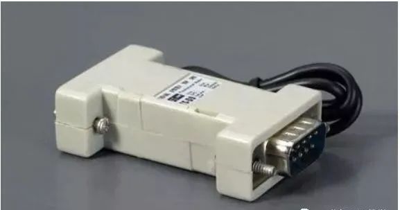
RS-232 is a serial physical interface standard established by the Electronic Industry Association (EIA) in the United States. RS stands for “Recommended Standard” in English, and 232 is the identification number. RS-232 specifies the electrical and physical characteristics that apply only to the data transmission path; it does not include the data processing methods. It is worth noting that many people often mistakenly refer to RS-232, RS-422, and RS-485 as communication protocols, which is incorrect. They are merely mechanical and electrical interface standards concerning UART communication (at most, they are at the physical layer of network protocols).
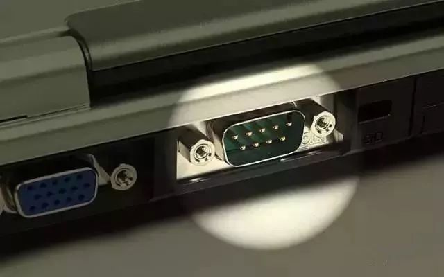
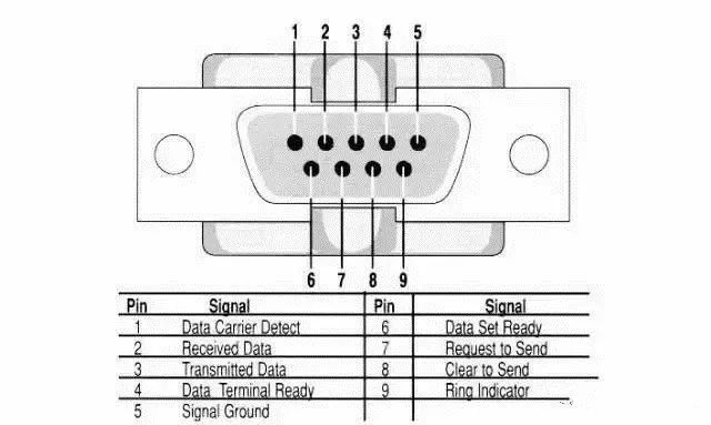
This standard specifies the use of a 25-pin DB-25 connector, detailing the signal content of each pin, and specifies the voltage levels for various signals. Later, IBM’s PC simplified RS-232 to a DB-9 connector, which became the de facto standard today. The RS-232 port in industrial control typically only uses three lines: RXD (2), TXD (3), and GND (5).
In the early days, since PCs all had RS-232 interfaces, we chose RS-232 when we needed to use UART. However, personal computers today, including laptops and desktops, no longer have RS-232 interfaces. People notice that there is no DB9 interface on the motherboard. Therefore, development boards now typically choose TTL UART or directly implement UART to USB on development boards.
In embedded systems, the serial port usually refers to the UART port, but we often confuse it with the COM port, as well as the relationships between RS232, TTL, etc. In fact, UART and COM refer to the physical interface form (hardware), while TTL and RS-232 refer to the voltage standards (electrical signals).
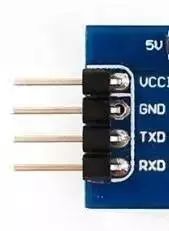
UART has 4 pins (VCC, GND, RX, TX), using TTL levels, with a low level of 0 (0V) and a high level of 1 (3.3V or above).
3. RS-485/RS-422 Standards
The RS-232 interface can achieve point-to-point communication, but this method cannot implement networking functions. To solve this problem, a new standard, RS-485, was developed. RS-485 uses differential transmission for its data signals, also known as balanced transmission, and it uses a pair of twisted wires, defining one wire as A and the other as B.
Typically, the positive voltage level between the sending driver A and B is +2 to +6V, representing one logical state, while the negative voltage level is -2 to 6V, representing another logical state. There is also a signal ground C, and RS-485 includes an