With the continuous development of low-light night vision technology, low-light night vision devices exhibit a wide variety, significant performance differences, and broad application fields. How to identify the main developmental lines among numerous low-light night vision devices has become a research hotspot for practitioners in this field. This article reviews the development history of generation zero, generation one, generation two, generation three, and super generation two low-light night vision devices. It summarizes the industry-recognized classification methods for these devices and proposes the concept of “generation four” low-light night vision devices. Additionally, it explains the positions of several atypical low-light night vision devices within the technology field, providing a “tree diagram” for readers to intuitively, accurately, and comprehensively understand the technical characteristics of each type of low-light night vision device and their positions in the technical field, serving as a reference for researchers engaged in low-light night vision technology.
Introduction
Since the emergence of generation three and super generation two low-light night vision devices, the American Litton Company publicly reported the concept of generation four low-light night vision devices, pointing out that it is characterized by a non-protective ion feedback film, automatic door control power supply, and small-diameter microchannel plates. This concept sparked widespread discussion among industry experts. However, after in-depth consideration, the concept of generation four low-light night vision devices was not widely adopted in the industry and soon faded away. In recent years, with the emergence of low-light complementary metal oxide semiconductor (CMOS) devices, electron bombardment active pixel sensors (EBAPS) digital low-light devices, aluminum gallium nitride photocathode blind ultraviolet image enhancers, indium gallium arsenide photocathode short-wave infrared responsive image enhancers, and other low-light night vision devices, the variety, performance differences, and application fields of low-light night vision devices have become increasingly complex, leaving non-technical professionals feeling “dizzy.” What exactly are generation four low-light night vision devices? What are the development trends of low-light night vision devices? How do low-light CMOS and other devices relate to super generation two and generation three low-light night vision devices? What positions do they occupy in the low-light night vision technology field? These questions have become focal points for decision-makers, implementers, and potential investors in the industry. This article reviews the industry-recognized development history of generation zero, generation one, generation two, generation three, and super generation two low-light night vision devices, summarizes the classification methods, proposes the concept of “generation four low-light night vision devices,” analyzes the technical characteristics of low-light CMOS and other devices, and outlines their positions in the low-light night vision technology field, providing strong support for a more intuitive, accurate, and comprehensive understanding of the technical characteristics of various low-light night vision devices.
1 Development History of Classic Low-Light Night Vision Devices
Classic low-light night vision technology studies the physical processes of photon-electron-photon image information conversion, enhancement, processing, and display under low illumination conditions at night. This technology allows people to see objects clearly at night as if it were daytime by using night sky light enhancement methods, enabling covert observation in the dark.
The working principle of low-light night vision technology is based on the differences in reflectivity of target objects to night sky light, achieving low-light imaging through photoelectric technology. Night vision technology began in the 1930s, truly developed in the 1950s and 60s, with the core device being the low-light image intensifier or low-light night vision device. With technological advancements, low-light night vision devices have successively experienced generation zero, generation one, generation two, generation three, and super generation two, each with distinct technical characteristics.
1.1 Generation Zero Low-Light Night Vision Devices
Generation zero low-light night vision devices are a type of external photoelectric effect imaging device. They appeared in the 1930s, with S-1 as the photocathode and silver-oxide-cesium as the material. This type of image intensifier is also known as an infrared image converter or image converter tube. It typically uses an electrostatic focusing structure, consisting of components such as a photocathode, focusing electrodes, and a phosphor screen, with two structural types: glass and metal. Its working principle is that the infrared photocathode converts the infrared light reflected from the target object into photoelectrons, which are accelerated by the electric field and bombard the phosphor screen, where the screen converts electrons into photons to form a visible light image, ultimately achieving the structure shown in Figure 1. Due to the low conversion efficiency of the Ag-O-Cs photocathode, it requires an active infrared light source, increasing the system’s volume and weight, and making it easy to expose oneself in combat, leading to limited use. The principle of the active infrared night vision system is illustrated in Figure 2.
Figure 1 Structure of Generation Zero Low-Light Night Vision Device
Figure 2 Working Principle of Active Infrared System
Technical characteristics include a silver-oxide-cesium photocathode prepared on the inner surface of the glass window, a double cylindrical electrostatic lens, and a flat glass planar phosphor screen. The photocathode has low sensitivity, and active infrared illumination easily exposes the user, making it less practical in combat.
1.2 Generation One Low-Light Night Vision Devices
Generation one low-light night vision devices are also external photoelectric effect imaging devices. They emerged in the 1960s, with S-20 as the photocathode and materials such as double alkali antimony potassium and multi-alkali antimony potassium sodium. These low-light night vision devices consist of a photocathode, electron lens, and phosphor screen employing an electrostatic focusing structure, as shown in Figure 3. Their working principle is that the photocathode generates corresponding photoelectron images under the excitation of input photons from the scene, converting weak or invisible radiation images into electronic images. Inside the ultra-high vacuum tube, the electron optics system applies a strong electric field to the photoelectrons, energizing them and focusing them with the electron optical lens to bombard the phosphor screen, creating a much stronger light intensity than the incident light, resulting in a photon image visible to the human eye, ultimately achieving the effect of converting invisible light into enhanced visible light images, realizing spectral conversion and energy enhancement functions. Due to the low single-stage gain (approximately 50 times), a three-stage cascade method is typically used (as shown in Figure 4). Compared to generation zero low-light night vision devices, generation one devices are passive observation methods characterized by good concealment and significantly improved imaging quality. However, they have drawbacks such as large volume, significant imaging distortion, sensitivity to strong light, and halo effects.
Figure 3 Single-Stage Generation One Low-Light Night Vision Device
1—Photocathode panel; 2—Photocathode outer tube; 3—Phosphor screen panel
Figure 4 Three-Stage Cascade Generation One Low-Light Night Vision Device
Technical characteristics include a fiber panel spherical structure multi-alkali photocathode, double spherical electron lens, and fiber panel spherical structure phosphor screen. The photocathode has low sensitivity, single-stage tube gain is low, and the three-stage cascade is large in volume and weight, allowing for passive imaging.
1.3 Generation Two Low-Light Night Vision Devices
In the 1970s, micro-channel plate (MCP) electron multipliers emerged, leading to the development of MCP image intensifiers, also known as generation two low-light night vision devices. The significant difference from generation one is the use of micro-channel plates (MCP) as electron multipliers. A micro-channel plate is a thin glass plate with many micro-channel holes, each containing a secondary electron multiplication layer made of high electron multiplication coefficient materials, achieving electronic multiplication of up to 106 on a glass plate less than 1 mm thick. The two common structures are close-packed MCP and electrostatic focusing MCP low-light night vision devices, as shown in Figures 5 and 6.
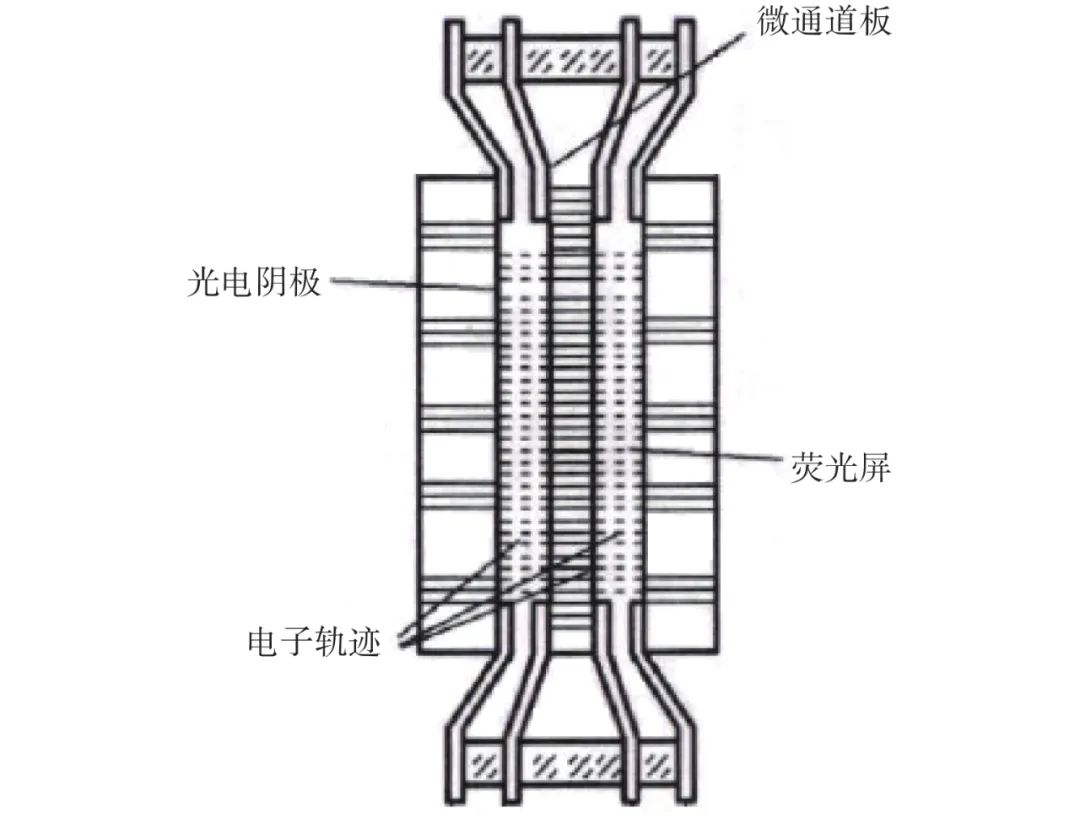
Figure 5 Close-Packed MCP Image Intensifier
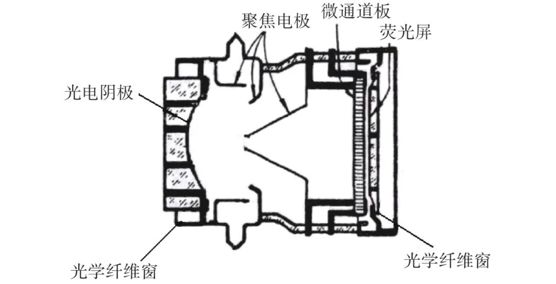
Figure 6 Electrostatic Focusing MCP Image Intensifier
Close-packed MCP low-light night vision devices have the advantages of uniform image quality both on and off-axis, distortion-free images, a magnification of 1, no pincushion distortion, small size, and low weight, with automatic strong light protection. However, due to the small structural spacing, to avoid field-induced emission, the applied voltage is limited to 300 V to 400 V, resulting in significant light feedback. The electrostatic focusing MCP low-light night vision devices have the advantages of being able to form inverted images, good modulation transfer function, higher resolution, and sufficient space for placing absorbent materials, extending their working life, and automatic strong light protection. However, they are large and heavy, making them unsuitable for head-mounted weapon systems.
Technical characteristics include fiber panels or glass spherical/planar structure multi-alkali photocathodes, micro-channel plates as electron multipliers, and fiber panels or glass spherical/planar structure phosphor screens, allowing for passive imaging. Compared to generation one low-light night vision devices, generation two devices are smaller and lighter; gain can be continuously adjusted by changing the voltage across the MCP; and the MCP’s current saturation characteristics allow for automatic strong light protection. Typical integral sensitivity is 450 μA/lm, typical resolution is 30 lp/mm, and typical signal-to-noise ratio is 14. There is still room for improvement in photocathode sensitivity, resolution, and signal-to-noise ratio indicators.
1.4 Generation Three Low-Light Night Vision Devices
Generation three low-light night vision devices are MCP low-light night vision devices with double close-packed focusing electron optical systems, composed of a transmission-type NEA GaAs photocathode (negative electron affinity, NEA, gallium arsenide, GaAs), generation three MCP with Al2O3 ion barrier film, and fiber panel phosphor screen components, with close-packed structures between the photocathode and MCP input surface, and between the MCP output surface and phosphor screen input surface, as shown in Figure 7.
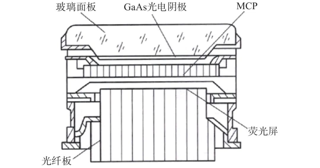
Figure 7 Structure of Generation Three Low-Light Night Vision Device
Generation three low-light image intensifiers have three major technical characteristics. 1) Negative electron affinity gallium arsenide photocathode. The vacuum energy level of this photocathode is lower than the conduction band bottom energy level in the semiconductor, forming a negative electron affinity. Electrons excited by photons exchange energy with lattice phonons, “thermalizing” to the conduction band bottom, and then escaping into vacuum, generating photon current. The negative electron affinity photocathode has advantages such as high quantum efficiency, low dark emission, concentrated energy distribution and angular distribution of emitted electrons, long-wave tunability, and great potential for long-wave response extension. These “thermalized electrons” in the negative electron affinity photocathode have much longer lifetimes than “hot electrons” in the positive electron affinity photocathode of generation two. Therefore, the negative electron affinity photocathode has a much larger escape probability than the positive electron affinity photocathode, resulting in higher sensitivity, reaching 800 μA/lm to 2400 μA/lm, improving more than 1.5 to 2 times compared to generation two photocathodes. 2) Generation three MCP. The MCP used in generation three low-light night vision devices exhibits high gain, low noise, and long lifespan, with a tri-aluminum oxide ion barrier film plated on the electronic input end face. This film can prevent residual gas molecules and positive ions generated during the MCP electron multiplication process from feedback, thus protecting the photocathode. Additionally, due to the presence of the aluminum oxide film, some energy from the input electrons is lost, resulting in a decrease in MCP gain, necessitating the use of higher gain MCPs. 3) Automatic door control high-voltage power supply. A compact integrated high-voltage power supply is an essential component of low-light night vision devices, providing the necessary operating voltages for various device levels in a small size and low power consumption, while also featuring auto-brightness control (ABC) and bright source protection (BSP) functions for the phosphor screen. The ABC circuit provides the phosphor screen output brightness required for comfortable observation by the human eye, with an adaptation range of 10−5 lx to 102 lx; for local strong light inputs (e.g., battlefield artillery, city lights, and car lights), a bright source protection circuit is required. Without altering the MCP and working voltage photocathode, the circuits for ABC, BSP, and pulse width adjustment of the average working voltage of the photocathode are collectively referred to as gate control circuits. The function of this circuit is to implement ABC, BSP, suppress ion feedback, and extend device lifespan. Due to generation three low-light night vision devices having high sensitivity and a spectral response well-matched to the night sky light spectrum distribution at extremely low illumination (10−4 lx), equipping them in low-light night vision instruments significantly enhances the effective range, especially under extremely low illumination. Since the 1980s, military forces in the US and Europe have successively equipped generation three low-light night vision instruments, achieving satisfactory results superior to previous generations during the 1983 Falklands War and the 1991 Gulf War, further promoting the large-scale production and equipping of generation three low-light night vision devices and equipment.
1.5 Super Generation Two Low-Light Night Vision Devices
Super generation two low-light night vision devices are developed based on generation two low-light night vision devices by introducing high-sensitivity (600 μA/lm to 800 μA/lm) multi-alkali photocathodes, consisting of MCPs and compact high-voltage power supplies, typically in a double close-packed structure, as shown in Figure 8. The noise factor of the micro-channel plate decreases, the output signal-to-noise ratio improves, and the overall MTF of the tube is enhanced. In recent years, France has introduced micro-nano grating technology into multi-alkali photocathode components to further improve super generation two performance, enhancing the efficiency of external light utilization, achieving breakthroughs in sensitivity, and extending the long-wave threshold of spectral response, thereby improving the overall performance of super generation two low-light night vision devices.
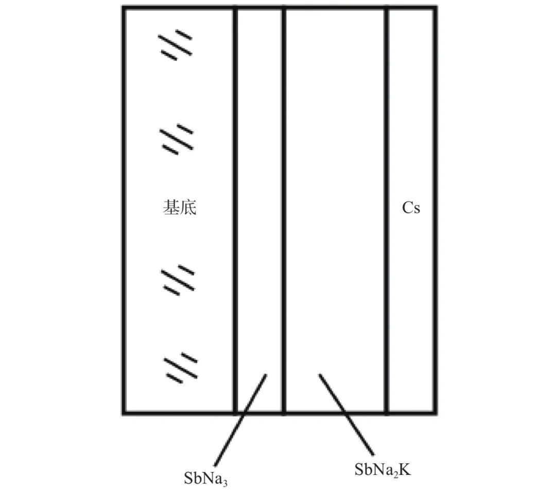
Figure 8 Structure Diagram of Super Generation Multi-Alkali Photocathode
Technical characteristics include a super generation thickened near-infrared extended multi-alkali photocathode, sensitivity of 500 μA/lm to 650 μA/lm; double close-packed electron optical systems, single-sided thermal indium sealing structure; application of low-noise MCP, integral sensitivity of 650 μA/lm to 1200 μA/lm, resolution of 64 lp/mm to 72 lp/mm, and signal-to-noise ratio of 25 to 28.
2 Atypical Low-Light Night Vision Devices
Atypical low-light night vision devices currently fall into two categories. The first category maintains the same working mechanism as classic low-light night vision devices, replacing the visible light-responsive photocathode with a non-visible light-responsive photocathode, while other electron multiplication and display methods remain unchanged. The second category differs from the working mechanism of classic low-light night vision technology, involving special processing of semiconductor devices to extend the lower limit of operating illumination, achieving application under limited low-light conditions.
In the first category, devices responsive to X-rays, ultraviolet light, blue-green light, and short-wave infrared light first convert non-visible light into electrons, then utilize the mature electron multiplication and display methods from classic low-light night vision devices to form low-light night vision devices responsive to non-visible light spectra, achieving detection and imaging of weak radiation in non-visible spectra, used in special fields such as X-ray image enhancers, ultraviolet image enhancers (cesium telluride/cesium rubidium photocathode image enhancers, aluminum gallium nitride/gallium nitride photocathode image enhancers), blue-green light-responsive image enhancers (gallium arsenide phosphide photocathode image enhancers), and short-wave infrared-responsive image enhancers (indium gallium arsenide photocathode image enhancers). In the second category, low-light CMOS and electron multiplying CCD (EMCCD) are included, which are specially processed based on conventional CMOS and CCD technologies to shift the detection illumination threshold downward, achieving low-light detection and imaging under limited low-light conditions.
2.1 “Generation Two Family” Low-Light Night Vision Devices
The “generation two family” low-light night vision devices are derived from the technical system of generation two low-light night vision devices, maintaining the device structure while replacing the photocathode type, resulting in devices responsive to non-visible light spectra. For example, cesium telluride (cesium rubidium) photocathode night vision devices are developed based on the structure and components of generation two multi-alkali photocathode low-light night vision devices, replacing multi-alkali photocathodes with cesium telluride (cesium rubidium) photocathodes, resulting in ultraviolet-responsive night vision devices in the ultraviolet wavelength range (200 nm to 320 nm). Due to the change in photocathode materials, the spectral response range shifts from visible light to ultraviolet light, and the indicator system transitions from photometric to radiometric, making it impossible to achieve a one-to-one comparison with the technical indicators of generation two low-light night vision devices, thus not fitting into the classic classification system of low-light night vision devices.
2.2 “Generation Three Family” Low-Light Night Vision Devices
The “generation three family” low-light night vision devices are derived from the technical system of generation three low-light night vision devices, maintaining the same device structure while replacing the photocathode type, resulting in devices that do not completely match the GaAs spectral response. These mainly include aluminum gallium nitride (gallium nitride) photocathode image enhancers, gallium arsenide phosphide photocathode image enhancers, and indium gallium arsenide photocathode image enhancers. They are developed based on the structure and components of generation three negative electron affinity GaAs photocathode low-light night vision devices, replacing the GaAs photocathode with aluminum gallium nitride (gallium nitride) photocathodes, gallium arsenide phosphide photocathodes, or indium gallium arsenide photocathodes, fully leveraging the technical advantages of adjustable long-wave thresholds based on Al component variation, resulting in ultraviolet-responsive devices in the ultraviolet wavelength range (200 nm to 280 nm), blue-green light-responsive devices in the blue-green light wavelength range (400 nm to 600 nm), and short-wave infrared-responsive devices in the short-wave infrared wavelength range (900 nm to 1060 nm). The structure and manufacturing principles of these three types of photocathodes are fundamentally the same as GaAs photocathodes, and due to the spectral response range transitioning from visible light to ultraviolet, blue-green light, and short-wave infrared light, the indicator system also transitions from photometric to radiometric, making it impossible to achieve a one-to-one comparison with generation three low-light night vision indicators, thus not fitting into the classic classification system of low-light night vision devices.
2.3 Low-Light CMOS
Low-light CMOS is based on traditional CMOS technology, processing signals within pixels, amplifying them, and reading them out with low noise, outputting imaging results in a digital form. To address the low fill factor defect of CMOS image sensors, a micro-lens or micro-wedge is fabricated above each pixel to focus the incident light energy onto the photoelectric conversion sensitive surface, thereby improving the sensitivity of CMOS image sensors, forming low-light CMOS, with its structure and working principle illustrated in Figure 9. By combining micro-lenses with CMOS, the sensitivity of the light-sensitive components is effectively enhanced, improving image quality under low-light conditions. However, due to high noise in the internal photoelectric effect process, imaging can only occur in environments with illumination above 10−2 lx. This meets the demand for low-light night vision equipment needed for basic tasks such as nighttime simulation training, marching, maneuvering, and maintenance in relatively high illumination environments. Additionally, due to the strong compatibility of CMOS technology and its scalability for production, it effectively reduces costs, making it a low-cost, small-sized low-light night vision device that can be used under certain illumination conditions without combat.
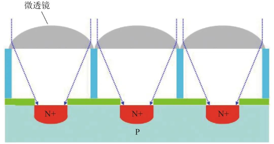
Figure 9 Principle Diagram of Low-Light CMOS
2.4 Electron Multiplying CCD
Electron multiplying charge coupled devices (EMCCD) consist of a CCD imaging storage area, serial register, multiplication register, and readout amplifier, belonging to frame transfer or full-frame transfer area array devices, employing “on-chip gain” technology to overcome the impact of readout amplifier noise on the signal, improving the signal-to-noise ratio and imaging quality. The internal structure of the EMCCD chip is shown in Figure 10. The working principle of the EMCCD differs from that of a conventional CCD, as shown in Figure 11. In a conventional CCD, the serial shift register directly passes the image signal from the active area to the output terminal for signal amplification and A/D conversion to display the video image. In an EMCCD, the image electronic signal in the serial shift register must first be amplified with low noise in the gain register before being passed to the output terminal for subsequent processing and A/D conversion to display the video image. Compared to conventional CCDs, the EMCCD chip has a special gain register located between the transfer register and output amplifier. The potential well of the second stage of electronic transfer is replaced by a pair of electrodes, with a fixed voltage on the first electrode and a high voltage added to the second electrode at a standard clock frequency, generating a transfer signal through the high voltage difference between the two electrodes, causing impact ionization and forming new electrons. Although the number of new electrons generated by each ionization is not large, multiple ionizations can significantly increase the number of electrons.
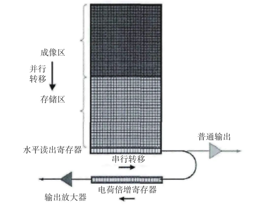
Figure 10 Internal Structure of EMCCD Chip
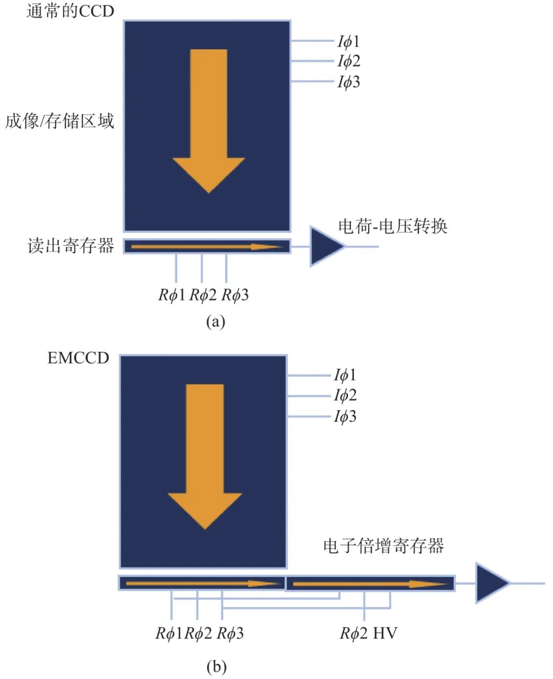
Figure 11 Comparison of Working Principles between Conventional CCD and EMCCD
Depending on the varying light conditions during application, EMCCD operating modes can be categorized into three types: 1) Conventional mode: When light conditions are relatively strong and can meet the imaging requirements of conventional CCDs, the electron multiplication function of the EMCCD can be turned off, allowing it to operate in conventional mode. At this time, the high voltage applied to the multiplication electrode is reduced to the same level as other gate electrodes, and the output signal of the EMCCD is equivalent to that of a conventional CCD. 2) Linear mode: When light conditions weaken, resulting in a decrease in input signal, when the signal decreases to a certain extent and the output signal’s signal-to-noise ratio significantly drops, the multiplication function can be activated, allowing it to operate in linear mode. By adjusting the gain settings of the multiplication register, the gate voltage of the multiplication electrode changes accordingly, effectively multiplying the input signal under the avalanche multiplication effect of the strong electric field, improving the output signal’s signal-to-noise ratio. 3) Photon counting mode: When light conditions are extremely weak, light radiation can be viewed as a flow of distinguishable photons. Since the signal generated by a single photon is very weak, effective signal recovery from a single photon cannot be achieved. To prevent the weak single photon signal from being drowned in readout noise, the gain of the EMCCD must be maximized.
The EMCCD is characterized by reduced noise reading from the substrate, high quantum efficiency (over 90%), minimal exposure time, and reduced excitation intensity requirements. Since its imaging unit is still a CCD, the imaging results can be digitized and output in CCD format.
3 Generation Four Low-Light Night Vision Devices
3.1 Research on Typical Classification Methods for Low-Light Night Vision Devices
3.1.1 Summary of Typical Classification Methods for Low-Light Night Vision Devices
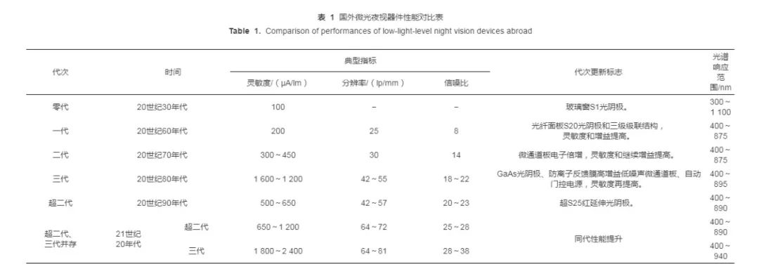
To propose classification methods for low-light night vision devices, a comparative analysis will be conducted based on typical indicators, generational update markers, and spectral ranges for foreign low-light night vision devices, as shown in Table 1.
Summarizing the content shown in Table 1, it can be concluded that the industry-recognized classic classification methods for low-light night vision devices have the following characteristics:
1) From the development history of generation zero, generation one, generation two, super generation two, and generation three, it can be seen that as the generational order number increases, core indicators such as sensitivity, resolution, and signal-to-noise ratio progressively improve, and the overall performance of low-light night vision devices also enhances. This has been confirmed through experiments. In a certain project, under conditions of (1 to 3) × 10−4 lx, the effective range of devices equipped with domestic generation three low-light night vision devices was more than twice that of devices equipped with domestic super generation two low-light night vision devices. Under (1 to 3) × 10−3 lx conditions, the effective range of devices equipped with domestic generation three low-light night vision devices improved by more than 30% compared to those equipped with domestic super generation two low-light night vision devices.
2) The spectral response range of typical low-light night vision devices is defined within the visible and near-infrared regions (400 nm to 1100 nm), and the integral sensitivity indicator is used to characterize the photoelectric conversion efficiency of their photocathodes, belonging to photometric physical quantities.
3) During each update and iteration, a typical new component will first replace the original component, and the performance changes of the new component will inevitably lead to significant improvements in the performance of low-light night vision devices. For example, the emergence of fiber panels replaced glass in generation one low-light night vision devices, enabling the possibility of generation one three-stage cascade low-light night vision devices, significantly enhancing gain; the emergence of MCP components used as electron multipliers in generation two low-light night vision devices allowed for electronic gain multiplication while substantially reducing the volume and weight of low-light night vision devices; the introduction of GaAs photocathode components in generation three low-light night vision devices replaced the multi-alkali photocathodes of generation two, resulting in a significant increase in integral sensitivity and a substantial improvement in signal-to-noise ratio.
Based on the above three points, it is evident that generation four low-light night vision devices should maintain the same spectral response as generation three devices, namely the GaAs photocathode, while introducing a new component to replace one or two components in the MCP and phosphor screen, forming a new device with a significant performance change compared to generation three low-light night vision devices.
3.1.2 Discussion on Domestic and Foreign Classification Methods for Low-Light Night Vision Devices
Foreign concepts of generation four low-light night vision devices have been proposed but have not been widely recognized in the industry. There are several representative concepts: 1) Low-light night vision devices with InGaAs/InP transmission electron near-infrared (0.9 μm to 1.060 μm) photocathodes; 2) bTe/PbSnTe composite array infrared photocathode STIRP—thermal infrared image converter (8 μm to 14 μm/3 μm to 5 μm); 3) Improved MCP materials based on generation three low-light night vision devices to enhance gain and sensitivity; 4) Evaluation based on quality factor for classification according to the size of the quality factor. Domestically, Zhou Liwei and others have pointed out that using “generation” classification to represent the performance of low-light night vision devices is overly general and imprecise, suggesting that the concept of “generation” should be downplayed in favor of using “quality factor” for quantitative description of low-light night vision device levels. Jin Weiqi and Pan Jingsheng have published research results on classification methods for low-light night vision devices, referencing the concept of “quality factor” proposed by some foreign scholars, using quality factors to evaluate the performance of low-light night vision devices, without considering the technical characteristics of low-light night vision devices. This approach reflects some practical ideas, but there are aspects worth discussing: 1) The quality factor equals the product of the limit resolution and signal-to-noise ratio, where limit resolution and signal-to-noise ratio are test data under two different working states, and multiplying the two values lacks physical significance and cannot represent the practical performance of low-light image intensifiers in specific environments. Limit resolution typically refers to the spatial resolution corresponding to a modulation transfer function drop to 3%. During testing, the input illumination is adjusted so that the phosphor screen can see the maximum and clearest resolution target lines, indicating the highest resolution. Usually, the input illumination during testing is 5 × 10⁻³ lx to 1 × 10⁻² lx, and the corresponding input illumination for each tested low-light night vision device’s limit resolution may vary and is not required to be the same. For signal-to-noise ratio testing, it is required to illuminate the photocathode of the low-light night vision device with a light spot of diameter φ0.2 mm at an illumination of 1.08 × 10⁻⁴ lx, with each tested low-light night vision device requiring the same input illumination, and it must be the same. Comparing the test conditions of these two parameters shows significant differences; multiplying two parameters operating at completely different illumination levels lacks much scientific basis and has no practical physical significance, warranting further discussion. 2) For low-light night vision devices, which achieve photoelectric conversion, multiplication, and display under low illumination, the primary functionality is visibility (determined by signal-to-noise ratio), followed by clarity (determined by resolution). Therefore, it is only valuable to compare limit resolution when visibility is ensured. Field tests of low-light night vision devices at night have demonstrated that when both devices can see, the one with higher limit resolution performs better; as illumination decreases, the one with a higher signal-to-noise ratio performs better, and the limit resolution becomes irrelevant. Therefore, using quality factors to represent the performance of low-light night vision devices is debatable.
3.2 Concept of Generation Four Low-Light Night Vision Devices
Currently, super generation two and generation three low-light night vision devices have been in development for many years, and advancing to generation four low-light night vision devices has become a consensus among many researchers and decision-makers. What are the specific technical characteristics of generation four low-light night vision devices? This has become a focal point of industry interest. Accordingly, this article summarizes the development history of typical low-light night vision devices and the technical characteristics of each generation, and based on the previously summarized three features of low-light night vision device classification methods, proposes that generation four low-light night vision devices should be GaAs photocathode EBAPS digital low-light night vision devices. The reasons are as follows:
1) Analyzing the structural composition, GaAs photocathode electron bombardment APS digital low-light night vision devices retain the GaAs photocathode of generation three low-light image intensifiers, replacing the MCP and phosphor screen with a new back-thinned electron-sensitive APS.
2) The spectral response of the GaAs photocathode is within the visible light range, belonging to the photometric domain, and its sensitivity performance can be compared with that of generation three low-light devices.
3) The back-illuminated APS replaces the functions of MCP electron multiplication and phosphor screen electro-optical conversion in generation three low-light night vision devices. This component integrates the functions of electron multiplication, electron transmission, and signal readout, enabling the ability of generation three low-light night vision devices to output simulated images to transition to digital image output capability, allowing low-light night vision devices to achieve a generational leap from “analog output” to “digital output,” enabling multiple users to jointly share images from a distance, better meeting the requirements for joint operations in the new era. Additionally, by using a photocathode gating power supply, the photocathode does not operate under high external illumination, with APS/CMOS operating based on internal photoelectric effects, and under low external illumination, the photocathode operates based on external photoelectric effects. These two operating modes alternate to leverage the technical advantages of both, achieving performance improvements, making it a digital low-light night vision device that can operate in all weather conditions.
The working principle of GaAs photocathode electron bombardment APS low-light night vision devices is that the photocathode converts input photons into photoelectrons, which are accelerated under static electric voltage to bombard the back-illuminated electron-sensitive APS chip, generating electron-hole pairs, forming electron bombardment semiconductor (EBS) gain. Since EBAPS consists only of the photocathode and APS, the image transmission chain is short, and the noise generated by EBS gain is much lower than the electronic multiplication noise of MCP. This reduces size and weight while significantly improving signal-to-noise ratio and MTF. Since its output end is APS, the imaging results are digitized and output in APS format. APS is a type of CMOS, where each pixel position internally has an amplifier, allowing its performance to convert discrete charge signals into voltage output even under very low bandwidth conditions, and it only requires resetting at frame rates, thus having low bandwidth requirements and high signal-to-noise ratio advantages, making it widely used under electron bombardment conditions, with the working principle illustrated in Figure 12.
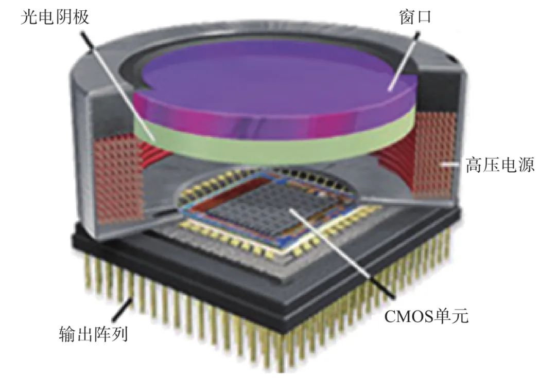
Figure 12 Structure Diagram of EBAPS
3.3 Tree Diagram of Low-Light Night Vision Devices
Based on the above research, a distribution tree diagram of various low-light night vision devices is presented in Figure 13.
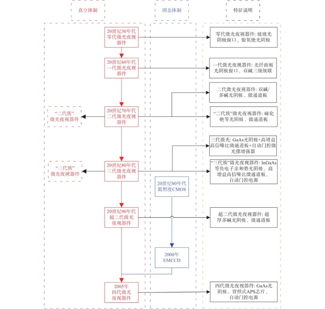
Figure 13 Distribution Tree Diagram of Various Low-Light Night Vision Devices
4 Conclusion
This article reviews the development history of generation zero, generation one, generation two, generation three, and super generation two classic low-light night vision devices, summarizing the three characteristics of the industry-recognized classification methods for classic low-light night vision devices. Using these three characteristics, it proposes that generation four low-light night vision devices refer to GaAs photocathode EBAPS digital low-light night vision devices, marking the transition of low-light night vision devices from the “analog” era to the “digital” era. This shift is also a focus of current international development and application in military low-light detection imaging. The imaging mechanisms and technical characteristics of several atypical low-light night vision devices are analyzed, and the concepts of “generation two family” and “generation three family” are proposed. A distribution tree diagram based on the technical characteristics of various low-light night vision devices is created, illustrating their respective positions in the field of low-light night vision devices. The research results hold certain reference significance.
Author: Cheng Hongchang, Shi Feng, et al.

New Optoelectronics

Long press the QR code to follow us
Welcome to reprint, please indicate the source!
Welcome to follow the “Applied Optics” public account
Welcome to reprint, please indicate the source!