Follow+Star Public Account, don’t miss exciting content
Author | strongerHuang
WeChat Public Account | strongerHuang
The CAN bus was initially mainly used in the automotive and industrial control fields. With the continuous maturity of CAN bus technology, it is no longer limited to the automotive industry and is now widely used in aerospace, medical, robotics, and various other fields.
Occasionally, readers ask:
-
-
What is the difference between CAN and serial port?
-
Are there any learning materials for CAN bus?
Today, we will discuss several important knowledge points about the underlying aspects of the CAN network: CAN bus baud rate, bit timing, and frame types.
The CAN bus is a type of asynchronous communication, which means it has a communication baud rate, generated by the baud rate generator located inside the CAN controller. We do not need to understand how it is generated, but we need to understand its meaning. This chapter will cover the following two points for beginners.
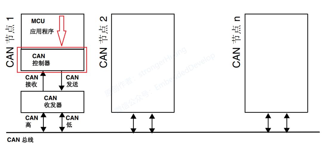
The position of the CAN controller in the CAN network is shown in the figure below:
1. Asynchronous Communication
In serial communication, it is mainly divided into asynchronous communication and synchronous communication.
Synchronous Communication: Communication where devices transfer data through a synchronization signal (CLK clock) is called synchronous communication. For instance, in I2C and SPI communications, there is a clock signal. Actually, in STM32, USART also has synchronous capabilities, but most of us only use its asynchronous functionality.
Asynchronous Communication: Simply put, it is when communication devices agree on the same time to send and receive data. This time will determine the baud rate discussed in this section.
Many engineers have not fully understood what baud rate means, so I will briefly explain its meaning in conjunction with UART baud rate.
In electronic communication, baud refers to the modulation rate, which is the rate at which effective data signals modulate the carrier, that is, the number of times the carrier’s modulation state changes per unit time. It is a measure of the symbol transmission rate, 1 baud means transmitting 1 symbol per second.
UART transmits 240 characters per second, and each character format contains 10 bits (1 start bit, 1 stop bit, 8 data bits), so the baud rate is240Bd, and the bit rate is10 bits * 240 characters/second = 2400bps.
From the above description, we can summarize:
Bit Rate: The number of binary bits transmitted per unit time;
Baud Rate: The number of symbols transmitted per unit time;
Only when each symbol represents one bit of information can the baud rate and bit rate be numerically equal, but their meanings are not the same.
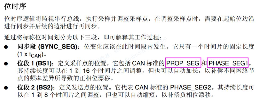
The previous chapter discussed baud rate, and the bit timing determines the size of the baud rate discussed in this section. In the CAN standard, one bit can be divided into 4 segments:
-
Synchronization Segment (SS)
-
Propagation Time Segment (PTS)
-
Phase Buffer Segment 1 (PBS1)
-
Phase Buffer Segment 2 (PBS2)
These segments are composed of the minimum time unit called Time Quantum (Tq).
One bit is divided into 4 segments, and each segment is composed of several Tq, which is called bit timing.
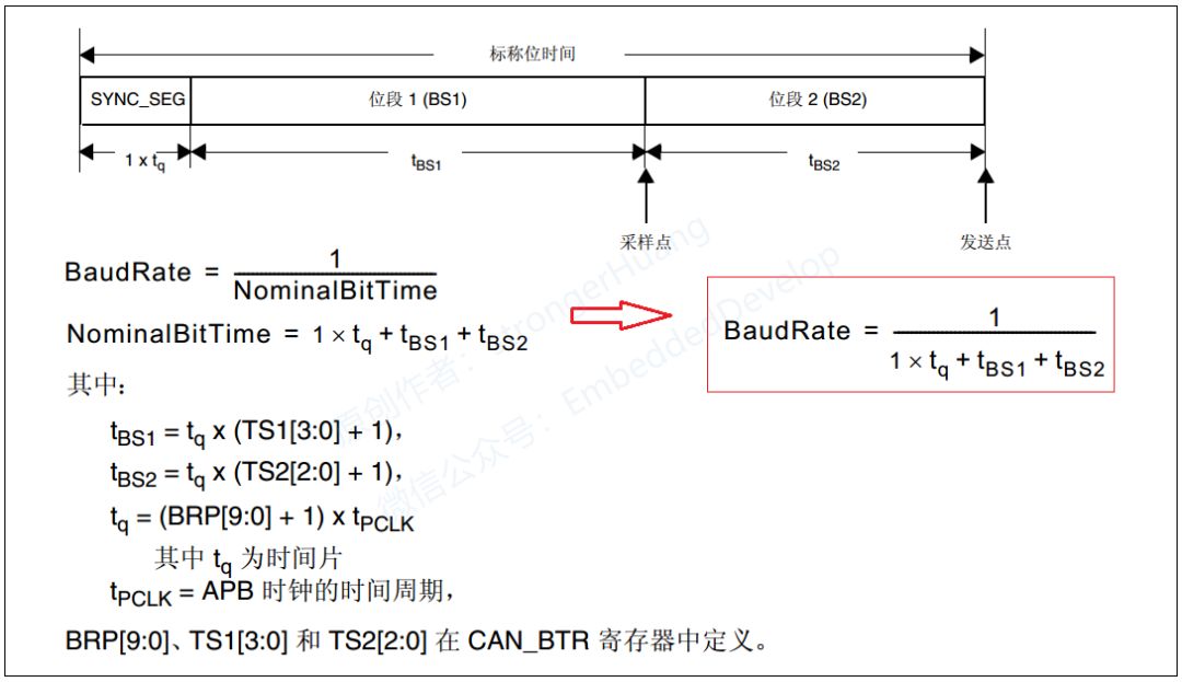
In the STM32 reference manual, the bit timing is divided into three segments, but it combines the propagation segment and bit segment 1 together, as shown in the figure below:
The number of Tq that one bit consists of and how many Tq each segment consists of can be set arbitrarily for the bit timing. By setting the bit timing, the transmission baud rate is determined:
These parameters will be configured in future programming to determine the communication baud rate.
Regarding synchronization, there are operations such as hardware synchronization and re-synchronization. However, beginners do not need to understand too much; mastering the basic content above is sufficient. More information about bit timing can refer to the ISO 11898 standard.
Frame Types and Format Description
The CAN bus communicates through the following 5 types of frames:
Data Frame: A frame used to send data from the sending unit to the receiving unit.
Remote Frame: A frame used by the receiving unit to request data from the sending unit with the same ID.
Error Frame: A frame used to notify other units of an error when an error is detected.
Overload Frame: A frame used by the receiving unit to notify that it is not ready to receive.
Frame Interval: A frame used to separate data frames and remote frames from previous frames.
Data frames and remote frames have both standard and extended formats. The standard format has an 11-bit identifier ID, while the extended format has a 29-bit ID.
1. Data Frame
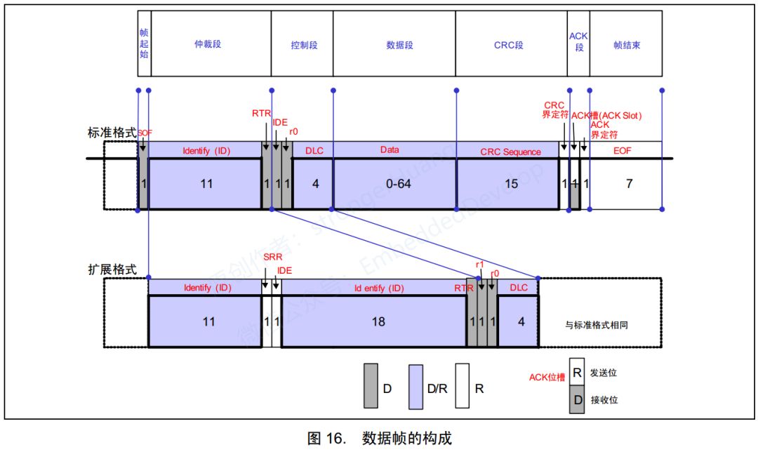
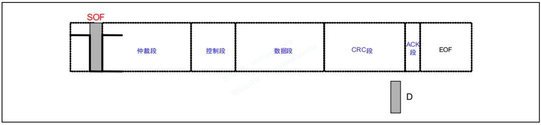
As shown in the figure, the data frame consists of 7 segments:
(1) Frame Start
Indicates the segment where the data frame begins.
(2) Arbitration Segment
Indicates the segment representing the priority of the frame.
(3) Control Segment
Indicates the number of bytes of data and reserved bits.
(4) Data Segment
Contains the data, which can send 0 to 8 bytes of data.
(5) CRC Segment
Checks for transmission errors in the frame.
(6) ACK Segment
Indicates confirmation of normal reception.
(7) Frame End
Indicates the segment where the data frame ends.
Understanding the meaning of the data frame starts with a thorough understanding of its definition: a frame used to send data from the sending unit to the receiving unit.
In general CAN bus communication, most of the time on the bus, data frames are used. For example, in the CANOpen protocol, the most frequently used PDO (Process Data Object) communication is done through data frames.
Beginners can first understand data frames, and then the rest will be easier to understand. Next, let’s discuss the details of the 7 segments of the data frame.
Frame Start
The standard and extended formats are the same. It indicates the segment where the frame starts, which consists of 1 bit of dominant level (as shown in the figure below):
For information on dominant and recessive levels, please refer to my previous article on differential signals.
There are dominant and recessive levels on the bus.
When executing the logical